background image

7

1.800.627.4499

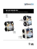
GR90, EV90, EV90P

ERV

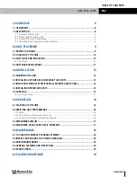
1.0 OVERVIEW 

9

1.1 DEFINITIONS .......................................................................................................9
1.2 DESCRIPTION ......................................................................................................9

1.2.1 Purpose of an ERV System .........................................................................................................9
1.
2.2 When Should You Use Your ERV ..................................................................................................9
1.
2.3 Using an ERV with Air-Conditioning ............................................................................................9
1.
2.4 Controlling Excess Humidity During Cold Weather .......................................................................9

2.0 UNIT PLACEMENT 

9

2.1 BEFORE YOU BEGIN .............................................................................................9
2.2 LOCATION OF THE UNIT .....................................................................................10
2.3 DUCT SIZES AND INSULATION ............................................................................10

2.3.1 Duct Sizes ............................................................................................................................... 10

2.4 DUCTWORK APPLICATIONS ................................................................................11

3.0 INSTALLATION 

13

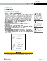
3.1 MOUNTING THE UNIT 

13

3.2 INSTALLING OUTSIDE AIR AND EXHAUST AIR DUCTS ..........................................14
3.3 INSIDE DUCTWORK SYSTEM (FOR WALL MOUNTED UNITS ONLY) ........................14
3.4 INST
ALLING RETURN AIR DUCTS ........................................................................14
3.5 CONTROLS ........................................................................................................15

3.5.1 Installing Controls .................................................................................................................... 15

4.0 OPERATION 

16

4.1 STARTING UP THE UNIT 

16

4.2 VERIFYING UNIT PERFORMANCE ........................................................................16

4.2.1 Airflow .................................................................................................................................... 16
4.2.2 Use Static Taps to Measure Airflow Rates ................................................................................ 16
4.2.3 Use Damper to Balance Airflow to Desired Rates ...................................................................... 16

4.3 MEASURING AIRFLOW .......................................................................................17
4.4 MEASURING CROSS CORE STATIC PRESSURE ....................................................17

5.0 MAINTENANCE 

18

5.1 TO CLEAN THE ENERGY EXCHANGE ELEMENT ....................................................18
5.2 INSPECT AND CHANGE THE FILTERS REGULARLY ................................................18
5.3 MOTOR MAINTENANCE ......................................................................................19
5.4 GENERAL CLEANING AND INSPECTION ...............................................................19
5.5 SERVICE PARTS .................................................................................................19

6.0 FACTORY ASSISTANCE 

19

TABLE OF CONTENTS
Summary of Contents for RenewAire ERV Series

Page 1: ...tage Controls Line Cord Model GR90 Galvanized Case Line Voltage No Line Cord Model EV90P High Performance Unit Painted Case Low Voltage Controls Line Cord GR90 EV90 EV90P GR EV SERIES ERV Installation Operation and Maintenance Manual ...

Page 2: ...ith all applicable building health and safety code requirements 5 Connect this unit only to a 120 VAC grounded receptacle protected by a 15 or 20 amp circuit breaker Do not remove the unit s line cord 6 Do not install unit or controls where they can be reached from a tub or shower 7 This unit must be properly ducted to the outdoors 8 Outside air inlet for this unit must be located away from source...

Page 3: ...Aire DO NOT SCALE DRAWING REMOVE ALL BURRS BREAK SHARP EDGES APPLICABLE STANDARDS DIM AND TOL ANSI Y14 5 TITLE DRAWING NO SCALE REVISION SHEET DATE BY KMC 04 30 15 3 DEG 005 015 63 Z ULTI 3000 WHITE SEE MATERIAL KMC MF LABEL SERIAL EV90 9 20 12 140088_000_D02 1 1 A 1 OF 1 MATERIAL FINISH LINEAR HOLE SIZE SURFACE FINISH UNLESS OTHERWISE SPECIFIED DIMENSIONS AND TOLERANCES ARE IN INCHES 4510 Helgese...

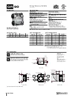
Page 4: ...8 Minimum Service Area Door can be Removed from Hinges 22 1 4 Minimum Service Area 21 1 4 Door Swing 2 5 8 7 8 Typ 21 7 8 Case 6 Nominal Typ 8 Nominal Typ 25 1 2 Overall with Hanging bracket Formed Inlet Ring LEFT VIEW FRONT VIEW RIGHT VIEW TOP VIEW Model GR90 Drawing Type Unit Dimension Version JUN18 ABBREVIATIONS EA Exhaust Air to outside OA Outside Air intake RA Room Air to be exhausted FA Fres...

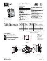
Page 5: ... Typ 24V AC Control Terminal 11 3 4 Typ 5 3 4 Typ 6 1 4 Typ 22 1 4 Minimum Service Area 10 1 8 Minimum Service Area Door can be Removed from Hinges 21 1 4 OA EA RA FA Door Swing 34 Line Cord Pressure Ports 4 Typ 23 3 4 Overall 11 5 8 Case 21 7 8 Case 6 Nominal Typ 8 Nominal Typ 7 8 Typ 2 5 8 25 1 2 Overall with Hanging Bracket Formed Inlet Ring LEFT VIEW FRONT VIEW RIGHT VIEW TOP VIEW Model EV90 D...

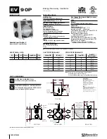
Page 6: ... AC Control Terminal 6 1 4 Typ 11 3 4 Typ 5 3 4 Typ OA EA RA FA 34 Line Cord Pressure Ports 4 Typ 23 3 4 Overall 23 5 8 Case 22 1 4 Minimum Service Area Door can be Removed from Hinges 22 1 4 Minimum Service Area Door Swing 8 Nominal Typ 6 Nominal Typ 7 8 Typ 2 5 8 21 7 8 Case 25 1 2 Overall with Hanging Bracket Formed Inlet Ring LEFT VIEW FRONT VIEW RIGHT VIEW TOP VIEW Model EV90P Drawing Type Un...

Page 7: ...E AIR AND EXHAUST AIR DUCTS 14 3 3 INSIDE DUCTWORK SYSTEM FOR WALL MOUNTED UNITS ONLY 14 3 4 INSTALLING RETURN AIR DUCTS 14 3 5 CONTROLS 15 3 5 1 Installing Controls 15 4 0 OPERATION 16 4 1 STARTING UP THE UNIT 16 4 2 VERIFYING UNIT PERFORMANCE 16 4 2 1 Airflow 16 4 2 2 Use Static Taps to Measure Airflow Rates 16 4 2 3 Use Damper to Balance Airflow to Desired Rates 16 4 3 MEASURING AIRFLOW 17 4 4 ...

Page 8: ...r Supply 12 Figure 2 4 2 Funace Return Air back into Return Air 12 Figure 2 4 3 RFurnace Return Air back into Supply Air EV90 P only 12 Figure 3 1 0 Mounting the ERV to a Stud Wall EV90 P only 13 Figure 3 5 0 Typical Control Schematic EV90 P only 15 Figure 4 2 0 Damper Installation 16 Figure 4 4 0 Airflow Diagram EV90 P 17 Figure 5 5 0 Service Parts EV90 P 19 TABLE OF CONTENTS TABLE OF ILLUSTRATIO...

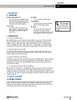
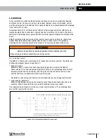
Page 9: ...ot the function of an ERV 1 2 2 When Should You Use Your ERV Use your ERV when windows are closed and you need to ventilate When the outdoor air is warmer or cooler than comfortable the ERV will allow a quieter more secure home with the windows closed and will also save energy 1 2 3 Using an ERV with Air Conditioning An ERV works very well with air conditioning because its enthalpy transfer energy...

Page 10: ...ervice Area Door can be Removed from Hinges 21 1 4 OA EA RA FA Door Swing 34 Line Cord Pressure Ports 4 Typ 23 3 4 Overall 11 5 8 Case Typ Typ FRONT VIEW RIGHT VIEW TOP VIEW ABBREVIATIONS EA Exhaust Air to outside OA Outside Air intake RA Room Air to be exhausted FA Fresh Air to inside INSTALLATION ORIENTATION Unit may be installed in any orientation NOTE 1 UNLESS OTHERWISE SPECIFIED DIMENSIONS AR...

Page 11: ...eas may be dampered so that they can be shut off when not in use A central location such as a hallway is also acceptable but won t clear humidity and odors from baths and kitchens as rapidly Locate stale air return grilles RA near the ceiling on inside walls Stale air returns are usually easiest to install in interior partitions u STALE AIR RETURN GRILLE SIZES u BATHROOM 4 x 10 or 6 x 10 40 to 60 ...

Page 12: ... may be operated separate from furnace blower FIGURE 2 4 0 SEPARATE ROOM AIR PICK UP FRESH AIR TO FURNACE RETURN AIR TRUNKLINE www renewaire com 800 627 4499 support renewaire com NOTE The furnace blower must be operated any time the ERV is operated Use furnace fan on continu ous low speed or optional FM control to cycle furnace fan on ERV FIGURE 2 4 2 FURNACE RETURN AIR BACK INTO RETURN AIR www r...

Page 13: ...ure the screws which you must supply are properly selected for the loads and substrate involved u MOUNTING THE EV90 P TO A STUD WALL Mount unit using supplied hanging bracket kit as described for mounting to concrete foundation wall u SUSPENDING THE EV90 P FROM FLOOR JOISTS OR TRUSSES The unit may be screwed directly to joists or trusses using the hanging bracket and integral flange Mount as descr...

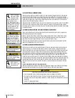
Page 14: ...is securely fastened and sealed to the duct collar DO NOT USE MORE FLEX DUCT THAN NECESSARY Flex duct is much more resistant to airflow than rigid duct longer runs of flex duct will reduce the ventilation performance of your system Stretch flex duct and avoid sharp bends Ducts connecting the unit to the outside must be well insulated Vapor barrier is required on both inside and outside of the insu...

Page 15: ...nnecting or servicing controls WARNING 3 5 1 Installing Controls The EV90 P is offered with a control board for connection to external controls The GR90 runs continuously whenever power is supplied to it u Optional Controls RenewAire offers a variety of controls specifically designed to work with the EV90 P These include PTL a two wire percentage timer FM a six wire percentage timer that will inte...

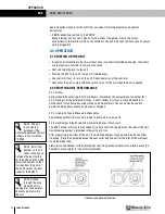
Page 16: ...manently install flow measuring stations and manometers These can also be used to determine when filters should be cleaned or changed 4 2 2 Use Static Taps to Measure Airflow Rates See Differential Static Across Core tables in Section 4 4 on page 19 4 2 3 Use Damper to Balance Airflow to Desired Rates if necessary The ERV s blower motors are well suited for volume control by dampers on the inlet o...

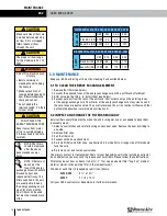
Page 17: ... Air OA port and the low pressure side to the Fresh Air FA port u To read SCFM of Room Air RA install the high pressure side of your measuring device to the Room Air RA port and the low pressure side to the Exhaust Air EA port u If gauge drops below zero reverse tubing connections u Use the reading displayed on your measurement device to cross reference the CFM output using the conversion chart NO...

Page 18: ... open Remove the door by sliding to one side 2 Remove filter clips 3 Pull the filters out 4 Vacuum with a hose attachment 5 Re install filters and filter clips see Section 5 5 Service Parts Orange side of filter should face the core 6 Re install door and fasten cam latches The primary contact for replacement filters for your RenewAire unit is the installing contractor As an alternative you may wis...

Page 19: ...n changing filters 1 Remove paper leaves etc from inlet and outlet screens 2 Inspect for insect nests 5 5 SERVICE PARTS ewaire com 800 627 4499 support renewaire com FIGURE 5 5 0 SERVICE PARTS EV90 P In the unlikely event that you need assistance from the factory for a specific issue make sure that you have the information called for in the Unit Information page in the front of this manual The per...

Page 20: ...liability derived from innovative design practices expert workmanship and Quick Response Manufacturing QRM As the pioneer of static plate core technology in North America RenewAire is the largest ERV producer in the USA We re committed to sustainable manufacturing and lessening our environmental footprint and to that end our Waunakee WI plant is 100 powered by wind turbines The facility is also on...

Reviews: