6
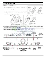
CASTER INSTALLATION
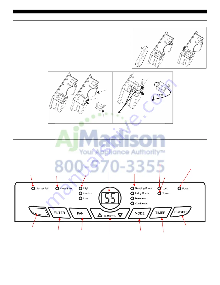
1) Remove casters from the bucket.
For the 70 Pint, the four casters can be taken out from the side
of the bucket directly. (Fig. 1)
For the 30 Pint and 45 Pint, the float must be removed first be-
fore taking the casters out. After taking out the casters, the float
must be placed back in the correct position in order for the de-
humidifier to function properly. (Fig. 2)
2) Tilt the dehumidifier no more than 45
⁰
and forcibly insert the casters. Make sure the ring around the caster
is flush against the bottom of the dehumidifier.
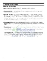
CONTROL PANEL & DIGITAL DISPLAY
POWER
BUTTON
INCREASE/DECREASE
ROOM
HUMIDITY LEVEL
TIMER
BUTTON
FILTER
BUTTON
FAN
SPEED
BUTTON
PRESET
MODE
BUTTON
Clean Filter
LED Indicator
Timer
LED Indicator
Fan Speed
LED Indicators
Child-Lock
LED Indicator
MyHome Mode
LED Indicators
Bucket Full
LED Indicator
Power On
LED Indicator
Digital Humidistat
Display
This button does
not operate or offer
any function
Fig. 1
4 casters in
plastic bag
packed inside
bucket
Fig. 2
Float
Bucket
Float
support
Two holes on the
float support
Two axes on the float
Float support
NOTE: The four casters can be taken
out by removing the float from pushing
the float support slightly outward.
NOTE: The two axes on
the float must be inserted
in the holes on the float
support.


