background image

5

INSTALLATION

Proper installation is the responsibility of the installer.

Product failure due to improper installation is not covered under the Warranty.

CHASSIS INSTALLATION

Units are shipped without a sleeve. In applications where unit is a replacement, it is recommended that a

GREE or 

Carrier sleeve be used.

These units can retrofit General Electric, Amana, Trane, and Friedrich sleeves/grilles (be sure outdoor
grille is installed on the sleeve). See Table 3 for details.
For

  any sleeve

retrofit applications, be sure that the foam seals (factory--installed on the tube sheets)

provide a good seal between the grille and outdoor coil tube sheets. These foam seals provide a barrier to

separate outdoor coil leaving air from mixing with the outdoor incoming air (known as air recirculation).

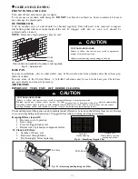
UNIT DAMAGE AND/OR OPERATION HAZARD

Failure to follow this caution may result in equipment

damage or improper operation.
For retrofit applications, foam seals on outdoor coil tube

sheets must make a seal between the coil and the grille or

loss of performance and premature damage to the major

components can result.

CAUTION

!

Table 3—Retrofit Wall Sleeves

Manufacturer

Wall Sleeve Part Number

General Electric

Metal Sleeve RAB71
Plastic Sleeve RAB77

Amana

Metal Sleeve WS900B

Trane

Metal Sleeve SLV149

Friedrich

T---Series Metal 11

1/2

---in. Deep Wall

Sleeve*
Standard Depth Wall Sleeve

16 X 42 X 13

3/4

---in. PXWS

* FR---SLEEVE---EXT accessory is required for retrofit into Friedrich

(T---Series) wall sleeves.

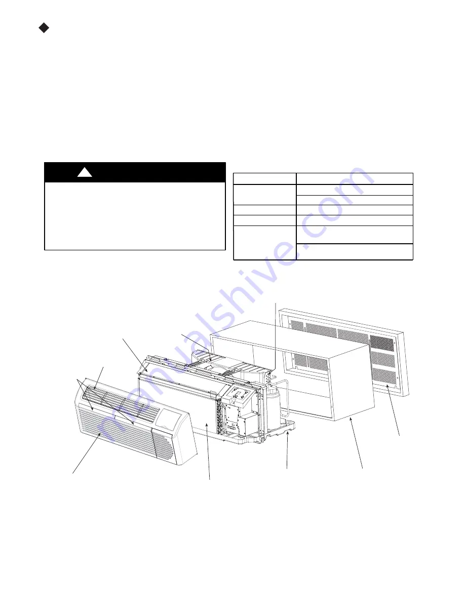
INDOOR

COIL

DISCHARGE
GRILLE

WIRE SCREEN

OUTDOOR
ORIFICE

COIL  TUBE
SHEETS

INDOOR-AIR

INLET

FILTERS

ACCESSORY

WALL

SLEEVE

ACCESSORY

OUTDOOR

GRILLE

Fig. 4 – Unit Components

FRONT

PANEL

BASEPAN

Summary of Contents for SG-PTAC-09HPDA

Page 1: ...R CONDITIONERS SG PTAC 15HPDA SG PTAC 12HPDA SG PTAC 09HPDA OWNER S MANUAL Packaged Terminal Air Conditioner before operating the unit and keep it for consultation For correct operation please read this owner s manual carefully Packaged Terminal Air Conditioner Heat Pump Model ...

Page 2: ...ol stands for the items should be followed The figures in this manual may be different with the material objects please refer to the material objects for reference SYSTEM CONFIGURATION HOW TO CONNECT SAFETY CONSIDERATIONS GENERAL INFORMATION UNIT FEATURES ELECTRICAL DATA INSTALLATION OPERATION CARE AND CLEANING PREVENTATIVE MAINTENANCE TROUBLESHOOTING LIMITED WARRANTY 1 1 4 2 5 10 11 14 15 16 17 1...

Page 3: ......

Page 4: ...on is not required change the configuration switch to turn the feature off see section on unit configuration Automatic defrost protection for heat pump models only When the outdoor temperature gets too cold approx 35 F and the unit can no longer effectively heat with the compressor the unit will automatically switch to electric heating The unit will then heat with electric heat until the outside t...

Page 5: ...ation heat only with Electric Heat Display Setpoint OR Room Temperature The unit can be configured to display the room temperature OR setpoint only during heating and cooling modes See section on unit configuration for more details Limit the Setpoint Range The unit can be configured to limit thecontrolling setpoint range The display will always showthecompletesetpointrange but the controlling setp...

Page 6: ...NAMEPLATE AMPS AWG WIRE SIZE 7 0 to 12 14 12 1 to 16 12 16 1 to 24 10 LEGEND AWG American Wire Gauge Single circuit from main box Based on copper wire at 60_C temperature rating Grounding For safety and protection the unit is grounded through the service cord plug or through separate ground wire provided on hard wired units Be sure that the branch circuit or general purpose outlet is grounded VOLT...

Page 7: ...h the outdoor incoming air known as air recirculation UNIT DAMAGE AND OR OPERATION HAZARD Failure to follow this caution may result in equipment damage or improper operation For retrofit applications foam seals on outdoor coil tube sheets must make a seal between the coil and the grille or loss of performance and premature damage to the major components can result CAUTION Table 3 Retrofit Wall Sle...

Page 8: ...RILLE This application has become more common due to pre manufactured windows with built in grilles or renovations where a GREE or Carrier sleeve is used with an existing non GREE grille Use of a GREE or Carrier wall sleeve with a non GREE grille requires installation of an Accessory Baffle Kit see Fig 8 which ensures a good seal between the unit and exterior grille to prevent air recirculation Ai...

Page 9: ...ll front panel See Fig 13 UNIT DAMAGE HAZARD Failure to follow this caution may result in equipment damage or improper operation Failure to remove shipping tape and screw will prevent fresh air vent door from opening and may result in damage to vent door cable CAUTION Shipping tape Fig 9 Shipping Tape Location Remove shipping screw if present Fig 10 Shipping Screw Location Pull out at the bottom t...

Page 10: ...stage call for heating from the wall thermostat the unit will automatically switch over to electric heating R W Y O Gh Gl C A07073 Fig 23 Terminal Connector Removal and Replacement Install Thermostat Wiring 1 Check to be sure power to unit is disconnected 2 Pull terminal connector to remove NOTE Terminal connector can be removed and replaced to simplify thermostat wiring 3 Connect wires from the t...

Page 11: ... be disabled under Freeze Guard protection See Fig 24 25 and Fig for terminal connections INTELLIGENT SELF CHECKING CONTROL Your GREE PTAC has a computer board that continuously checks key components of the unit to ensure they are operating properly Under normal operation unit status indicator STATUS on main PCB light is steadily ON If there is a major problem the unit will shut down and display a...

Page 12: ... Remove front panel See Fig 11 2 Remove junction box S Remove junction box cover by removing three screws from front Remove junction box by taking out top rear and side screws See Fig 14 3 Connect accessory power supply cord or hard wire connector to unit connector See Fig 15 S Units must be installed using the appropriate power supply kit See Table 4 POWER CONNECTION CHART These connections must ...

Page 13: ...fficiency Energy Tip Keep the vent control at CLOSE Room air will be filtered and circulated Open Close Vent Control Pull lever through label to operate Fig 17 Ventilation Control Location ADJUSTING AIR DIRECTION To adjust air direction 1 Remove front panel See Fig 11 2 Remove louver screws that hold louver insert in place from back side of front panel See Fig 18 3 Turn louver insert and rotate 18...

Page 14: ...de continuous or cycle CON Continuous Allows fan to run continuously circulating air even when the temperature setting has been satisfied This switch helps to maintain the room temperature closer to the thermostat setting CYC Cycle This setting allows the fan to cycle on and off with the compressor or electric heater The fan stops a short time after the temperature setting is satisfied Setpoint Te...

Page 15: ... the air temperature sensor bias is used to adjust the room air temperature reading when in cooling mode Not normally required Indoor Air Temperature Sensor Biasing forHeating mode Sometimes known as an anticipator the air temperature sensor bias is used to adjust the room air temperature reading when in heating mode Not normally required Indoor Temperature Display Changebetween showing setpoint o...

Page 16: ... at the requested level of comfort COOLER Lowers temperature Minimum temperature setting is 61_F 16_C WARMER Raises temperature Maximum temperature setting is 86_F 30_C 2 FAN SPEED MODE ON OFF FAN SPEED Set fan operation for HIGH MED LOW or AUTO speed MODE COOL For cooling MODE HEAT For heating NOTE If unit is a heat pump raising the heat setting 5_F will cause unit to use its electric heating ele...

Page 17: ...if necessary AIR FILTERS IMPORTANT TURN UNIT OFF BEFORE CLEANING UNIT DAMAGE HAZARD Failure to follow this caution may result in equipment damage or improper operation Do not operate unit without filters in place If a filter becomes torn or damaged it should be replaced immediately Operating without filters in place or with damaged filters will allow dirt and dust to reach indoor coil and reduce c...

Page 18: ...an both sides of outdoor coil Never use high pressure spray on coils S Clean basepan and outdoor vent filter S Clean outdoor orifice and fan S Clean indoor coil Never use high pressure spray on coils S Clean indoor fan wire screen and front panel S Clean or install new indoor air inlet filter s S Clean wall sleeve and outdoor grille S Inspect cord and receptacle S Secure electrical connections S E...

Page 19: ... heat or gatherings of people make room uncomfortable S Close vent door S Check dipswitch settings for desired comfort Wait approximately 3 minutes for compressor to start DISPLAY HAS STRANGE NUMBERS CHARACTERS ON IT The unit may be in a diagnostic condition Check Intelligent Self checking Control section to determine if unit has had a failure The unit may be set for _C instead of _F see the keypa...

Page 20: ...of God or normal wear and tear Warranty service must be performed by a qualified HVAC contractor Soleus maintains a centralized service network to provide parts and assist in resolving service problems if difficulties are encountered Soleus agrees to provide service information sell repair parts and reimburse the dealer servicer for parts and services in accordance with Soleus International s Poli...

Reviews: