IM0005-00
1.
Do not attach radio connection to radio until housing has
been fully threaded into enclosure.
2.
If lightning suppressor is used, connect to output side of
the coupler.
3.
Antenna and cable connections should be finger
tightened only. Over tightening can cause permanent
damage resulting in equipment failure.
4.
RX series antenna couplers with M25 straight threads
(RX*M) must be secured from loosening when installed
in an Ex d enclosure. Use of LOCTITE® or similar sealing
adhesive is acceptable and shall be applied to threaded
joint prior to mounting the RX antenna coupler to the Ex
d enclosure so the joint is secured against loosening.
PRODUCT SPECIFICATIONS
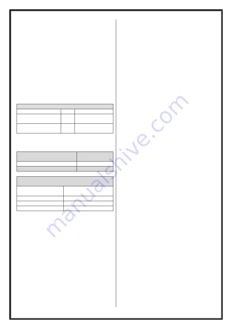
Ambient temperature range
Max RF Power Input (Pi)
Dust
Gas
6 W
37.8 dBm
100
-
40°C ≤ Ta ≤ +80°C
-
40°C ≤ Ta ≤ +
65°C
2 W
33 dBm
80
-
40°C ≤ Ta ≤ +
85°C
-
40°C ≤ Ta ≤ +
70°C
Refer to product marking for
max RF Power Input (Pi) allowed
and related ambient temperature
Maximum Fault Voltage (Um)
250 VDC
250 VAC 50-60 Hz
Frequency Range
≤ 6 GHz
Impedance
50 Ω
Maximum RF Threshold Power
(table 4 in IEC/EN60079-0)
ATEX/IECEx
Equipment Group
Threshold Power
Group I, IIA, III
6 W (37.7 dBm)
Group IIB
3.5 W (35.4 dBm)
Group IIC
2 W (33.0 dBm)
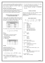
MAXIMUM RF INPUT POWER (Pi)
Refer to product marking for maximum RF Input Power (Pi)
allowed (see product specification table above).
This value do not consider any cable loss between the RF
transmitter and the RX coupler and may therefore be
considered as the maximum allowable RF transmitter output
power when the RX coupler is directly connected to a RF
transmitter.
Added cable loss between the RF transmitter and the RX
coupler may allow the RF transmitter output power to exceed
the value above as long as the cable loss ensures the power
at the input of the RX coupler is less than or equal to the
above values.
𝑅𝐹 𝑡𝑟𝑎𝑛𝑠𝑚𝑖𝑡𝑡𝑒𝑟 𝑜𝑢𝑡𝑝𝑢𝑡 𝑝𝑜𝑤𝑒𝑟
(𝑑𝐵𝑚)
− 𝐶𝑜𝑎𝑥 𝑐𝑎𝑏𝑙𝑒 𝑙𝑜𝑠𝑠
(𝑑𝐵)
≤ 𝑀𝑎𝑥𝑖𝑚𝑢𝑚 𝑅𝐹 𝐼𝑛𝑝𝑢𝑡 𝑃𝑜𝑤𝑒𝑟 (𝑃𝑖)
It is permissible limited the maximum power output of the
transmitter by a programmable or software setting but it
must not be possible for an end-user to override it.
MAXIMUM PERMITTED
RF THRESHOLD POWER (Pth)
The RF threshold power, sometimes called the effective
isotropic radiated power (EIRP), as defined in IEC/EN60079-0,
is the product of the effective output power of a radio
transmitter multiplied by the power gain of a connected
antenna. The maximum threshold powers for each
equipment group as defined by Table 4 in IEC/EN60079-0 are
provided above.
Because most antennas list the gain relative to an isotropic
radiator (dBi) instead of the raw power gain, it is often easier
to simply add the antenna gain in dBi to the radio output
power in decibel-milliwatts (dBm). Any added cable loss
between the RF transmitter output and the RX input, or the
RX output and the antenna may also be factored in.
𝑃𝑡ℎ
(𝑑𝐵𝑚)
= 𝑅𝐹 𝑇𝑟𝑎𝑛𝑠𝑚𝑖𝑡𝑡𝑒𝑟 𝑜𝑢𝑡𝑝𝑢𝑡
(𝑑𝐵𝑚)
+ 𝐴𝑛𝑡𝑒𝑛𝑛𝑎 𝐺𝑎𝑖𝑛
(𝑑𝐵𝑖)
− 𝐶𝑎𝑏𝑙𝑒 𝑙𝑜𝑠𝑠 𝑏𝑒𝑡𝑤𝑒𝑒𝑛 𝑅𝑎𝑑𝑖𝑜 𝑎𝑛𝑑 𝑅𝑋
(𝑑𝐵)
− 𝐶𝑎𝑏𝑙𝑒 𝑙𝑜𝑠𝑠 𝑏𝑒𝑡𝑤𝑒𝑒𝑛 𝑅𝑋 𝑎𝑛𝑑 𝑎𝑛𝑡𝑒𝑛𝑛𝑎
(𝑑𝐵)
▪
The resulting threshold power calculated by the above
formula MUST be below the threshold power for the
operating area group rating given above.
▪
Consideration of fault conditions in the radio transmitter
is not necessary. The max radio
transmitter’s RF power
output should be taken from manufacturer’s datasheet in
normal operation.
▪
A radio output power lower than those provided above
may be used to allow for an antenna with a higher gain.
▪
In case of device with multiple outputs and multiple
antennas, each threshold power is calculated separately
for each output/antenna.
▪
Gain of multiband antennas should be evaluated
separately at each individual frequency.
▪
High gain directional antennas on the same device should
not be directed in the same direction.
ANTENNA CONNECTION
The antenna connected to the RX coupler must be installed in
accordance with the earthing requirements of IEC/EN 60079-
14.
Antenna's earthing need to evaluate in function of RX coupler
series as follows:
Model RXF, RXN, RXS, RXT, RXB
In case of antenna direct mounting on RX coupler (without
coax cable) the antenna is earthed through the enclosure
earth connection via RX body.
Summary of Contents for RX Series
Page 4: ......


