IM0005-00
In case of remote antenna installation using a coax cable the
antenna need to be installed on an isolate earth support in
order to grant a single earth connection through the
enclosure earth connection.
Model RX1, RX2, RX3 (ISOLATE GROUND)
In case of antenna direct mounting on RX coupler (without
coax cable) the antenna ground is isolated from earth.
In case of remote antenna installation using a coax cable the
antenna can be earthed through adequate connection.
MAXIMUM JOULES CALCULATION IN CASE
OF COAX CABLE INSTALLATION
In case of coax cable installation (radio/SX coupler and SX
coupler/Antenna) the adding cable need to be evaluating to
ensure that the maximum energy stored on cable not
exceeded the value allowable per IEC/EN 60079-11:
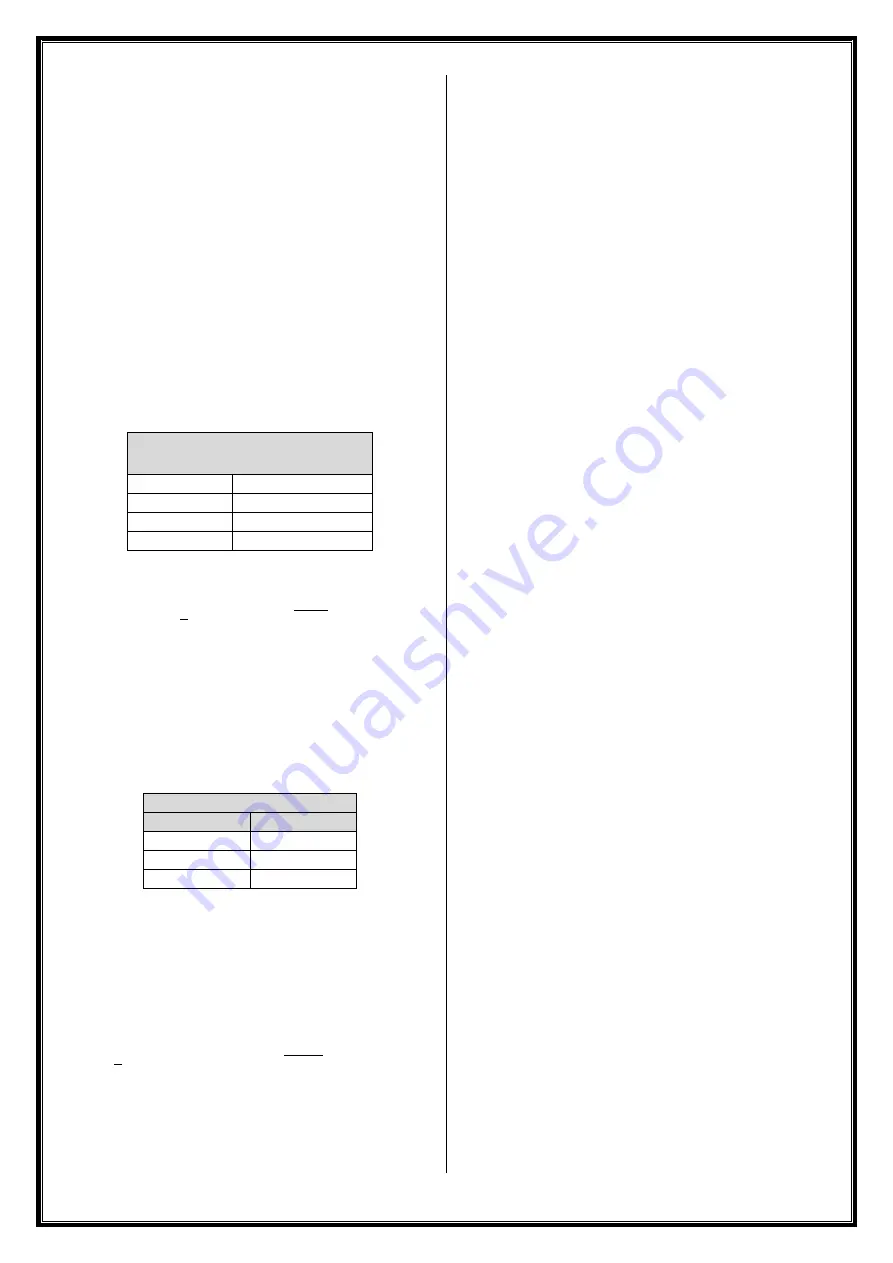
Max energy (Joules) allowed per
IEC/EN 60079-11
Group I
1500 μJ
Group IIA
950 μJ
Group IIB
250 μJ
Group IIC
50 μJ
The calculation can be done according to following equation:
𝐸 =
1
2
∗ {𝐶 ∗ [(1.5 ∗ (√𝑅 ∗ 𝑃)]
2
}
Where:
E = Energy
C= RX Capac Coax cable capacitance
(see below RX series reference value)
R = Impedance (50Ω)
P = Radio power output
1.5 = Safety Factor
RX Coupler capacitance
Type
pF
J
81.6
R
18
L
56.4
Example
RF Radio Power Output = 2 W
Antenna cable capacitance = 1195 pF
SX (J type) Coupler capacitance = 81.6 pF
Input cable capacitance = 73 pF
Total Capacitance C = 1349.6pF
𝐸 =
1
2
∗ {1349.6 𝑝𝐹 ∗ [(1.5 ∗ (√50 ∗ 2)]
2
} = 0.152𝜇𝐽
Answer = 0.152μJ acceptable for any Group
▪
The verification and maintenance of the electrical
equipment must be performed according to IEC/EN
60079-17.
▪
The user should guarantee the keeping of the safety
characteristic of the device after maintenance.
▪
The maintenance related the components used for wiring
must be performed according to manufacturer
instruction.
DISPOSAL / RECYCLING
Disposal and recycling of the product according to national
regulation for waste disposal and recycling.
WARNING: Do not dispose the product and the components
in the environment.
MODEL NOMENCLATURE
RX
X
X
X
XX XX
X
XX - XXXXX
1
2
3
4
5
6
7 -
8
1 Coupler Series
F
RP-SMA Female
N
N Female
S
SMA Female
T
TNC Female
B
BNC Female
1
N Female (isolate ground)
2
TNC Female (isolate ground)
3
BNC Female (isolate ground)
2 Threads
3
¾” NPT
M
M25x1.5
3 Material
S
AISI 303
C
AISI 316
L
AISI 316L
4 Coaxial Radio Connector
XX
varies, see sales literature
5 Coaxial Cable Length
00
no cable (direct RF connection)
XX
cable length in inches
6 Frequency Range
X
varies, see sales literature (type J, L or R)
7 Certification Mark
X0
ATEX / IECEx
XN
ATEX / IECEx and North America & Canada
standards (dual marking)
8 Special execution
XXXXX varies, consult Solexy
Summary of Contents for RX Series
Page 4: ......


