background image

6

7

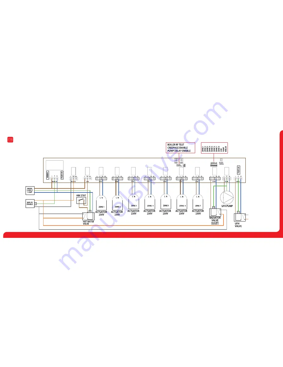
Wiring Centre

MODEL:

 UFH8-RF

Wiring Diagram UH8-RF

Summary of Contents for UH8-RF

Page 1: ...MODEL UH8 RF ...

Page 2: ... signal is received from a hot water time clock on the system only the H W output will become active This is a timed output which is normally fed to a cylinder thermostat then to a valve but could also be used for towel rails In either case the valve auxiliary switch would operate the boiler other heat source Other functions Creepage During hot weather the heating is not normally needed as often t...

Page 3: ... cylinder thermostat C common NO normally open NC normally closed Electrically this is a two way switch whatever supply is placed on the common connection is fed to the NC connection when there is no call for hot water This is then switched to the NO connection when there is a call for hot water Normally the NO connection would be wired to the hot water cylinder thermostat then from there to the h...

Page 4: ...6 7 Wiring Centre MODEL UFH8 RF Wiring Diagram UH8 RF ...

Page 5: ...neers test switches These are a block of 12 dip switches used to test each zone boiler pump and HW outputs To enable any output put the switch in the ON position When installation is complete all switches MUST be in the OFF position Record the rooms names connected to each zone with the zone number and record the channel number you have selected you will need this information when installing the t...

Page 6: ...10 11 Wiring Centre MODEL UFH8 RF Notes System Configuration ...

Page 7: ...Want More Information Call our support team on 44 0 1268 744 249 cations directly on our website www solfexufh co uk Rev 1 0 Slimline Products Commonly used with the UH8 wiring centre NeoStat DS SB TM4 ...

Reviews: