background image


500

1

2

14

0

50


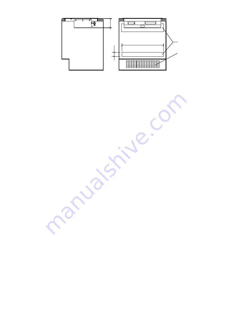
                                        side view   


      front view 


Fig. 5


Chart of 8ssembly 

1-VENTILATION AIR INLET,  2- VENTILATION AIR INLET WITH MESH  


REMARKS: 

- Due to the height of the hob, it is impossible to install it over an oven in standard kitchen 
cabinets.  
 - If the kitchen cabinet has a back wall, it is absolutely necessary to cut out ventilation openings in 
it, as shown 

on the drawing

.

fig. 5, 

- Because of the need to assure circulation of air, an air inlet grate should be installed in the skirting 
of the cabinet 

fig. 4.


2.3


Gas supply system  

1.


GPC-2 

have a vertical connector pipe ending with an R1/2” outside thread (ISO 7-R1/2) for 

connecting the hob to the gas supply system. It is recommended that the hob be connected to the 
gas supply system with a flexible connecting hose with a 

safety certificate

.


2.


If the hob is supplied by means of a flexible connecting hose, it is necessary to use an R ½ /G ½ 
screw-in/screw-on elbow. A cut-off valve must be installed in the system to stop the supply of 
gas to the hob, as well as a gas filter preventing the nozzles from clogging due to polluted gas.  

3.


If the hob is to be supplied with liquid gas from a gas cylinder, a ø10/R1/2” connector pipe is to 
be  screwed  into  the  gas  supply  connector  pipe,  after  removing  the  ½”  nipple.  A 

liquid  gas 

regulating valve 

needs to be installed on the cylinder valve. The regulating valve is connected 

with  the hob with  a flexible hose for liquid  gas  (max. length  3 m) with  clamps  on both  ends. 

The regulating valve and the flexible hose must have safety certificates.  
 

-

The above activities, for the sake of the user’s safety, should be performed by an authorized gas 

installation technician! 


2.4. Electric system  

 The control system of the hob is supplied with 12 V direct current through a power supply. In 
order to assure correct and safe operation of 

GPC-2

 hobs, it is necessary to provide an electric 

socket (230 V/50 Hz) close to the location of the stove in order to connect the hob’s power supply. 
The electric socket should have a grounding bolt and cannot be located directly over the hob, at the 
distance of less than 

10 cm away from the side 

of the stove and at least 

10 cm above 

the top plane 

of the hob plate, away from the area affected by 

hot fumes

 exhausted in the back of the hob.  

Moreover, it is necessary to provide properly ventilated place for the power supply.  In other 
places, a special cable to connect the hob with a 12 V DC system will be provided on request.  


3.   USE OF THE HOB 
 
3.1

 The startup of the hob should be performed by 

an authorized 

technician in the 

buyer’s 

home. 

Summary of Contents for GPC-2

Page 1: ...Sp z o o biuro solgaz com pl Assembly and operating instructions OF CERAMIC GAS HOB for kitchen furniture arrangement GPC 2 GPC 2 T ...

Page 2: ...ntal friendly parameters which you will be able to evaluate in the course of daily use Have fun with preparing your perfect tasty meals Yours sincerely SOLGAZ The ceramic gas panel cooker must be connected to a gas source by an authorized person certified installer Dear Sir Dear Madam We guarantee that your new gas fired heating panel will operate correctly However should you have any problems wit...

Page 3: ...intelligent reheating function 10 3 4 Switching off the burners 10 3 5 Switching the controller lock on and off 11 3 6 Residual heat indicator 11 3 7 Choice of pots 11 3 8 Utilization of combustion gas heat 12 3 9 Reduction of operating time 12 4 HOB CLEANING AND MAINTENANCE 12 4 1 Cleaning the ceramic panel 13 4 2 Cleaning the cooker strips 13 4 3 Control and supervision over gas electrical and v...

Page 4: ...of the power adapter 12V DC 3 5A Protection class of the housing IP 40 Dimensions L x W x D mm 330x495x110 The entire electrical installation of the hob is supplied with a special power pack and is prepared as a low voltage system In terms of fire risk the hob is classified as a safe device 1 3 Design of the gas hob The hob fig 1 has two injector gas burners rated as specified in the table above w...

Page 5: ... gas outlet 6 gas inlet 7 controller 8 power supply socket 9 power adapter Fig 2 control panel no 7 on fig 1 1 user lock 2 lock indicator 3 power setting 4 power setting indicator 5 6 burner selection fields 7 8 digital indicator of burner power settings 9 on off switch 10 on off indicator 11 timer indicator ...

Page 6: ...ssembly in furniture All activities related to the assembly and connection of the stove to the gas and electric systems must be performed by an authorized installation technician Assembly of the hob in kitchen countertops Due to the large size of the hob it is not recommended to install it in the countertops of individual kitchen cabinets A composite kitchen countertop where the gas hob is to be i...

Page 7: ... 150 470 40 60 0 1 min 38 495 330 110 4 8 Fig 3 Instalation min 15 mm min 15 mm 1 2 3 Fig 4 Hob with oven arrangement 1 VENTILATION AIR INLET IN THE BOTTOM PART OF THE SHELF 2 VENTILATION AIR INLET WITH MESH 3 AIR ...

Page 8: ... be screwed into the gas supply connector pipe after removing the nipple A liquid gas regulating valve needs to be installed on the cylinder valve The regulating valve is connected with the hob with a flexible hose for liquid gas max length 3 m with clamps on both ends The regulating valve and the flexible hose must have safety certificates The above activities for the sake of the user s safety sh...

Page 9: ...ers NOTE do not switch on the hob burners for a prolonged period without filled dishes put on the hot fields first Otherwise your device might be damaged When you choose any single burner by touching the controller activating field no 5 or 6 on fig 2 and set the power by touching the power setting slider no 3 fig 2 within a range exceeding 0 the selected burner will go on This is supposed to happe...

Page 10: ...g function The hob operating status with reheating is a transitory condition for rapid achievement of target temperature of the active hot field up to the heating power set It is signaled by the decimal point lighting up next to the active burner s digital indicator 5 6 fig 2 1 If any level of heating power is set for the given hot field the controller display will show a number corresponding to t...

Page 11: ...o 1 fig 2 twice within up to 2 seconds the signal LED no 2 fig 2 goes off the lock is off and a sound signal is emitted 3 6 Residual heat indicator After a hot field is shut down it remains hot for a certain time and the H message is displayed The above applies to all operating burners being shut down Do not touch the hot fields during that time and do not place heat sensitive items on the hot fie...

Page 12: ...This hot area can be used for warming up meals that do not require high temperature Use of this hot area significantly reduces the hob maintenance costs as we utilize the heat of combustion gas emitted from the burner Note the additional hot area is hot and you must remember it to avoid getting burnt when touching it do not allow boiling over of prepared dishes and avoid grease splashing on the ce...

Page 13: ... must not turn off a given heating field It is necessary to immediately precisely scrape off the leaving while they are hot with a sharp scraper from a hot heating field After the stain is removed one may turn off the stove and clean the cooled ceramic plate with a special cleaning agent A cleaning agent must never be applied on a hot ceramic plate Cleaning of the hob grids 1 The fume exhaust grid...

Page 14: ...ions are built in accordance with valid standards and regulations Note After installing the hob the installer must carry out initial startup During initial startup squealing can be heard at combustion gas outlet This is normal caused by gas feeding to gas tubes and burner It will disappear after first startup 5 2 Adapting the hob for different type of gas If the hob needs to be adjusted to a diffe...

Page 15: ...e of gas pressure drop in the network or cylinder the hob will be automatically locked This is signaled by the letter G 7 CONTROLLER ALARM CONDITIONS SIGNALING Alarm messages may display as a result of faults in hob operation or gas shortage in network Identifications of alarm conditions and controller s signals are given in Table 5 Table 5 Reason Identification Condition signal Overheated control...

Page 16: ...ed together with your hob Power supply adapter Our service center s phone no 48 074 856 52 88 serwis solgaz com pl correspondence address SOLGAZ Sp z o o 58 124 Marcinowice ul Spoldzielcza 3 Poland TYPE GPC 2 GPC 2 T SERIAL NUMBER INSTALLERS SIGNATURE DATE ...

Reviews: