22
SOLID AIR ® INTERNATIONAL
•
T +31 598 36 12 21
•
www.solid-air.com
•
contact@solid-air.nl
i
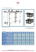
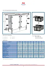
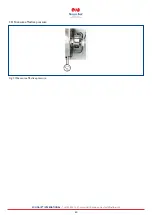
Position siphon-connector split unit
Dimension A
(mm)
Dimension B
(mm)
Dimension C
(mm)
Dimension D
(mm)
CPL-iV-4700
796
645
712
CPL-iV-6100
796
645
915
CPL-iH-4700
831
796
610
610
CPL-iH-6100
831
796
610
915
101
C
A
B
Ø40
D
228
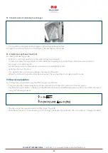
The effective height of the trap h (mm) must exceed the maximum underpressure or overpressure
at the condensate connector (1 mm WC = 10 Pa).
•
The trap drain line must not be connected directly to the public sewage system, but rather must be able to run out freely.
•
Vent longer drain lines to prevent condensate backing up in the line (provide additional vent in trap drain line).
Fig. 6.6 Trap types
>>
Fill the trap with water
.
h = 1.5 x p (mm WC) + 50 mm (minimum)
p
= Under- or overpressure in mm WC according to appliance design
50 mm (WC)
= Reserve (imprecision in design, evaporation)
1,5
= Additional safety factor
Ball trap
Trap

