54
SOLID AIR ® INTERNATIONAL
•
T +31 598 36 12 21
•
www.solid-air.com
•
contact@solid-air.nl
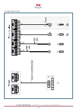
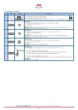
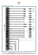
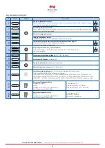
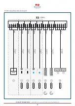
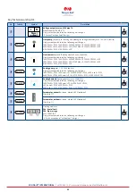
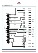
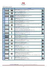
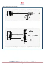
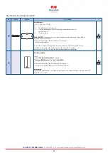
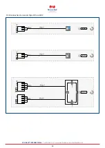
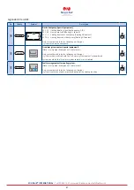
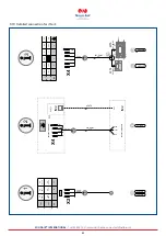
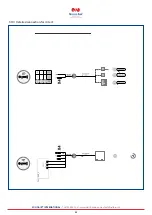
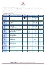
9.1.11 Overview of cables for onsite wiring
Listed cable cross-sections are minimum cross-sections for copper cables without taking into account the cable length
and onsite conditions.
Cable types must be selected according to the type of routing.
Never route cables for sensors, valves, servomotors (24V) together with 230/400V cables.
Alternatively, use shielded cables.
PLEASE NOTE:
(24V) cable - number of cores without green-yellow cores.
Description
Source
Name of component
Number of cores
Cross-section
Voltage
No.
W1
Power Supply onsite
1a
3
See chapter
6.8.2
230V
q
1b
5
400V
W2
X3
Power supply reserve
3
1,5
230V
2!
W12
X3
System messages
7
1,5
variable
2*
W13
X4
Bus connections
3
1,0
24V + shielding
2(
W14
X4
BMK-F
5
1,0
24V + shielding
3)
W15
X4
BMK
5
1,0
24V + shielding
3!
W16
X4
Auxiliary module
5
1,0
24V + shielding
3#
W19
X4
Room temperature sensor
2
0,5
24V
3$
W30
X4
Additional customer-supplied contact OFF
2
1,0
24V
3(
W31
X4
Additional customer-supplied contact ON
2
1,0
24V
4)4!4@
W37
X4
Fire protection group 1
2
1,0
24V
4#
W38
X4
Fire protection group 2
2
1,0
24V
4$
W39
X4
Fire protection group 3
2
1,0
24V
4%
W40
X4
Fire protection group 4
2
1,0
24V
4^
W41
X4
Smoke detector
2
1,0
24V
4&
W44
X3
Heat pump
3
1,5
230 V
2@
W45
X3
Heat/boiler demand
3
1,5
variable
2#
W46
X3
Cooling pump
3
1,5
230V
2$
W47
X3
Cooling demand
3
1,5
variable
2%
W48
X4
Heating actuating signal
3
1,0
24V
3%
W49
X4
Cooling actuating signal
3
1,0
24V
3^
W50
X8
Solid Air Link Pro
4
1,0
24V + shielding
4(
WE1
XE2
Onsite heat pump
4
0,5
24V
5)
WE2
XE1
Onsite heat pump
5
1,5
variable
5)
WE3
XE2
Fire alarm system contact
2
0,5
24V
5!
WE4
XE2
Coolunsystem fault message
2
0,5
24V
5@

