background image

5

SOLID AIR ® INTERNATIONAL


• 

T +31 598 36 12 21 

• 

www.solid-air.com 


contact@solid-air.nl 

2. SAFETY

>>

 The heat generator may only be worked on by contractors.

>>

 In accordance with VDE 0105 Part 1, work on electrical components may only be carried out by qualified electricians.

2.1 Intended use

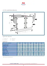
Solid Air CPL ventilation units are designed to heat and filter normal air. The maximum air intake temperature is  
+40 °C. The use of these units in wet rooms or rooms with explosive atmospheres is not permissible. Handling very dusty 
or aggressive media is not permissible.

Any onsite modification or improper use of the unit is not permissible and Solid Air GmbH accepts no liability for any 
damage caused as a result.

If additional protective equipotential bonding is required due to structural requirements, this should be provided 
onsite. The user or the certified electrician is obliged to ensure correct earthing of the appliances in accordance with the 
applicable national and local electrical and installation regulations.

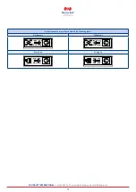
A conductive or non-conductive connection can be established between modules depending on the appliance 
configuration. Modules with electrical equipment must always be connected with the earth conductor.

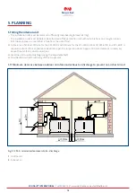
Ventilation units intended for internal installation must be placed in rooms that meet the requirements of VDI 2050 (VDI 
2050, Requirements for technical equipment rooms - Planning and execution). A contractor is defined as a qualified and 
properly trained installer, electrician, etc.
The user is defined as somebody who has been trained to use the heat generator by a specialist.

The appliance may only be used up to an elevation of 2000 m above sea level.
The cables used in the unit are silicone-free and cadmium-free. They meet fire safety standards of class Eca (DIN 60332-2).

2.2 Safety measures

Never remove, bypass or otherwise disable any safety or monitoring equipment. Only operate the heat generator if it is in 
perfect technical condition. Any faults or damage that impact or might impact safety must be remedied immediately by a 
qualified contractor.

>>

 All faulty components must be replaced with original Solid Air spare parts.

It may only be used for handling air. This air must not contain any harmful, combustible, explosive, aggressive, corrosive or 
otherwise dangerous substances, as these would be distributed throughout the duct system or building, where they could 
cause a risk to the health of, or even kill the occupants, animals or plants living there.

2.2.1 What to do in the event of a fire

The unit does not present a direct risk of fire. The small numbers of seals fitted inside the unit can burn away if subjected 
to external influences. 

>>

 If there is a fire, disconnect the appliance from the power supply using the onsite smoke detector.

>>

 Wear respiratory equipment if you fight a fire.

>>

 Use standard extinguishing agents such as water, extinguishing foam or extinguishing powder..

Summary of Contents for CPL 1400

Page 1: ...INSTRUCTIONS FOR CONTRACTORS TYPE CPL English subject to modifications 02 2022 6809530 202012 ...

Page 2: ...L iH specifications dimensions 11 4 3 CPL A 12 4 3 1 CPL A specifications dimensions 13 5 Planning 14 5 1 Siting the internal unit 14 5 1 1 Minimum clearance between outdoor air intake and exhaust air discharge to prevent an air short circuit 14 5 2 Siting the external unit weatherproof 15 5 2 1 Connecting the condensate drain pipe and PWW heat exchanger 15 5 3 Position of operating side 16 6 Inst...

Page 3: ... 34 8 3 1 Compact filter 34 8 3 2 Fan motor unit 35 8 3 3 Electrical equipment 35 8 3 4 Countercurrent plate heat exchanger PHE 35 8 3 5 Electric preheating coil electric reheating coil accessory 35 8 3 6 Bypass damper extract air damper outdoor air damper boost damper 35 8 3 7 Damper servomotors OPEN CLOSED or variable 35 8 3 8 Condensate pans 35 8 3 9 Trap 35 8 4 Hygiene CPL checklist 36 9 Appen...

Page 4: ...s responsible for the safekeeping of all documents The documents are provided by the contractor 1 5 Symbols The following symbols are used in this document Table 1 1 Meaning of the symbols 1 6 Warnings Warnings in the text warn you of possible risks before the start of an instruction The warnings provide you with information on the possible severity of the risk using a pictogram and a keyword Tabl...

Page 5: ...ents for technical equipment rooms Planning and execution A contractor is defined as a qualified and properly trained installer electrician etc The user is defined as somebody who has been trained to use the heat generator by a specialist The appliance may only be used up to an elevation of 2000 m above sea level The cables used in the unit are silicone free and cadmium free They meet fire safety ...

Page 6: ...ble documents to the operator Instruct the operator on how to operate the system Make the operator aware of the following Annual inspections and maintenance must be performed by a contractor Solid Air recommends concluding an inspection and maintenance contract with a contractor Repair work must be performed by a contractor Use only genuine Solid Air spare parts Do not make any technical changes t...

Page 7: ...fety requirements DIN EN 60204 1 Safety of machinery electrical equipment of machines DIN EN 60730 Automatic electrical controls DIN EN 61000 6 2 3 Electromagnetic Compatibility DIN EN 60335 1 VDE 0700 1 Safety of electrical appliances general requirements 3 2 The following standards and regulations apply to installation and operation DIN EN 50106 VDE 0700 500 Safety of electrical appliances tests...

Page 8: ...al pressure switch for filter monitoring 5 Countercurrent heat exchanger with bypass 6 EC fan supply air 7 Adjustable feet 8 PWW aperture 9 Connectors for DN 50 trap 10 EC fan extract air 11 Bypass damper with servomotor variable speed 12 Compact filter outdoor air 13 Filter pre dryer optional 14 Exhaust air damper with servomotor open close 15 Outdoor air damper with servomotor open close 16 Unit...

Page 9: ...1749 Height H mm 1017 1424 1424 1424 1424 Foot height mm 170 170 170 170 170 Damper height mm 128 128 128 155 155 Exhaust air 1 mm Intl 596 x 206 Intl 596 x 307 Intl 799 x 307 Intl 1222 x 356 Intl 1527 x 356 Outdoor air 2 mm Intl 596 x 206 Intl 596 x 307 Intl 799 x 307 Intl 1222 x 356 Intl 1527 x 356 Extract air 3 mm Intl 596 x 206 Intl 596 x 307 Intl 799 x 307 Intl 1222 x 356 Intl 1527 x 356 Supp...

Page 10: ...heat exchanger optional 5 Adjustable feet 6 PWW aperture 7 Connectors for DN 50 trap 8 EC fan extract air 9 Exhaust air damper with servomotor open close 10 Bypass damper with servomotor variable speed 11 Filter pre dryer optional 12 Outdoor air damper with servomotor open close 13 Compact filter outdoor air 14 Differential pressure switch for filter monitoring 15 Unit isolator 16 Control panel 17...

Page 11: ... T2 incl locks mm 732 732 Total height H1 mm 1309 1716 1716 1716 1716 Height H mm 1017 1424 1424 1424 1424 Foot height mm 170 170 170 170 170 Control mm 122 122 122 122 122 Exhaust air 2 mm Intl 612 x 409 Intl 612 x 612 Intl 815 x 612 Intl 1222 x 612 Intl 1527 x 612 Outdoor air 1 mm Intl 612 x 409 Intl 612 x 612 Intl 815 x 612 Intl 1222 x 612 Intl 1527 x 612 Extract air 3 mm Intl 612 x 409 Intl 61...

Page 12: ...ger with bypass 5 EC fan supply air 6 PWW heat exchanger 7 PWW connection 8 Base frame 9 Connectors for DN 50 trap 10 Boost damper with servomotor optional 11 Compact filter extract air 12 Differential pressure switch for filter monitoring 13 Intake hood outdoor air 14 Outdoor air damper with servomotor open close 15 Filter pre dryer optional 16 Compact filter outdoor air 17 Bypass damper with ser...

Page 13: ...780 Total depth T1 mm 815 815 1017 1425 1730 Total height H1 mm 1455 1860 1860 1860 1860 Length L mm 1525 2033 2033 2237 2237 Depth T mm 712 712 915 1322 1627 Height H mm 1021 1428 1428 1428 1428 Base frame mm 305 305 305 305 305 Extract air 2 mm Intl 612 x 409 Intl 612 x 612 Intl 815 x 612 Intl 1222 x 612 Intl 1527 x 612 Supply air 4 mm Intl 612 x 409 Intl 612 x 612 Intl 815 x 612 Intl 1222 x 612...

Page 14: ...risk of frost A clearance of at least 750 mm for the CPL 1400 and 950 mm for the CPL 2400 CPL 3300 CPL 4700 and CPL 6100 is required in front of the appliance to be able to open the inspection doors Approx 700 mm clearance is necessary above the unit for air duct connections Level the unit horizontally align using the adjustable feet Provide drain outlet for draining off the condensate 5 1 1 Minim...

Page 15: ...al unit Weatherproof units must not be used for any load bearing building functions or as a replacement for any part of the roof VDI 3803 5 1 DIN EN 13053 6 2 5 2 1 Connecting the condensate drain pipe and PWW heat exchanger With weatherproof units sited outdoors keep the condensate drain and DHW coil free of frost provide suitable protection if required i ...

Page 16: ...side Fig 5 1 Operating side 1 Exhaust air 3 Extract air 2 Outdoor air 4 Supply air CPL iV operating side supply air left CPL iV operating side supply air right CPL iH operating side supply air left CPL iH operating side supply air right CPL A operating side supply air left CPL A operating side supply air right ...

Page 17: ...air com contact solid air nl Air duct connections are identified with the following labels Outdoor air Exhaust air Extract air Supply air AUL ODA 6801059 48 10 AUL ODA ABL ETA ABL ETA 6801061 48 10 FOL EHA 6801062 48 10 FOL EHA ZUL SUP 6801060 48 10 ZUL SUP ...

Page 18: ...k the appliance for transport damage If there is any transport damage or a suspicion of damage the recipient must indicate this on the consignment note and have it countersigned by the haulier Report all transport damage to Solid Air immediately Dispose of the transport packaging in accordance with local regulations 6 1 1 Storage Store the ventilation in a dry area in temperatures between 25 C and...

Page 19: ...t least as long as the distance to the eye bolts or crossbar 6 3 Disposal and recycling When the appliance reaches the end of its service life it may only be dismantled by qualified personnel Before starting to dismantle the appliance disconnect the power supply Power cables must be removed by qualified electricians Sort and dispose of metal and plastic parts according to material types and in com...

Page 20: ...e frame must sit on the foundation Point loads are not permitted Provide permanently elastic noise insulation in the form of insulation strips between the installation surface and the base frame This provides insulation against structure born noise Fig 6 2 Insulation against structure borne noise for the building 1 Insulation against structure borne noise 3 Insulation if required 2 Roof membrane T...

Page 21: ...ertical accessory Afb 6 4 Square to round adaptor box Adaptor insulating collar for round duct connection for internal unit with horizontal air direction and weatherproof unit accessory Afb 6 5 Square to round adaptor insulating collar Install round duct systems on adaptor Insulate the ducts in accordance with applicable regulations and industry standards 6 6 Fitting the trap Position siphon conne...

Page 22: ...ceed the maximum underpressure or overpressure at the condensate connector 1 mm WC 10 Pa The trap drain line must not be connected directly to the public sewage system but rather must be able to run out freely Vent longer drain lines to prevent condensate backing up in the line provide additional vent in trap drain line Fig 6 6 Trap types Fill the trap with water h 1 5 x p mm WC 50 mm minimum p Un...

Page 23: ...down via the unit isolator The main terminals are live even when the ON OFF switch is in the OFF position Do not touch the EC fans for five minutes after disconnecting the power across all poles Use type B residual current protective devices with 300 mA as only these are suitable for DC residual currents Type A residual current protective devices are not suitable Press the test button every six mo...

Page 24: ...ability for any damage or loss resulting from technical modifications to Solid Air control units I If control voltage is present or a set speed is saved the EC fans will restart automatically after power failure 6 8 2 Power cable cross section onsite fuse protection 6 8 3 Motor data CPL 1400 2400 3300 4700 6100 Rated voltage 1 x 230 V 50 60 Hz 3 x 400 V 50 60 Hz 3 x 400 V 50 60 Hz 3 x 400 V 50 60 ...

Page 25: ...nstallation tubing to the M8 threaded holes on the back of the outdoor units Do not make any drilled holes in the unit matching cable duct available as optional accessory Lay the onsite cable to the control panel in the cable duct installation tube 1 M8 threaded holes 2 Cable duct fitted to threaded holes 3 Installation tube fitted to threaded holes ...

Page 26: ...fans will restart automatically after power failure DANGER Moving components Injuries can be caused by rotating fans or moving dampers Only work on the unit when it is disconnected from the power Only operate the unit once all safety features are in place and functioning properly NOTE Unqualified personnel System damage Commissioning and maintenance must be performed by a qualified contractor Acco...

Page 27: ...reset parameters To modify functions and parameters see the installation and operating instructions provided To modify functions and parameters see the operating instructions provided Check the following functions Check all inputs and outputs for correct wiring and function Frost protection function Fan rotational direction Outdoor air extract air damper rotational direction Plausible sensor value...

Page 28: ...ric preheating coil accessories The air volume must not be below the minimum level Minimum air volume CPL 1400 600 m h CPL 2400 1100 m h CPL 3300 1500 m h CPL 4700 2200 m h CPL 6100 2900 m h Follow the relevant safety regulations for electric heating coils The electric preheating coil must be protected from moisture and water The electric preheating coil filter pre dryer is activated by the contro...

Page 29: ...ers and exhaust air dampers are completely closed Extract air fan out of action The supply air fan is running and delivers the required flow rate When the set room temperature has been achieved the unit switches to standard control mode 7 3 Flow rate calculation The flow rate is calculated using the effective pressure method Compare the static pressure upstream of the inlet nozzle with the static ...

Page 30: ...30 SOLID AIR INTERNATIONAL T 31 598 36 12 21 www solid air com contact solid air nl 7 3 1 Measure effective pressure Fig 7 1 Measure effective pressure ...

Page 31: ...ctive pressure 1 Flow rate 2 Effective pressure Δp 7 3 3 CPL 2400 effective pressure K value of fan 93 Fig 7 3 CPL 2400 effective pressure 1 Flow rate 2 Effective pressure Δp Δp Pa 43 62 85 110 140 175 210 250 293 340 m h 500 600 700 800 900 1000 1100 1200 1300 1400 Δp Pa 74 115 166 226 295 375 463 560 666 m h 800 1000 1200 1400 1600 1800 2000 2200 2400 V V ...

Page 32: ...3300 effective pressure 1 Flow rate 2 Effective pressure Δp 7 3 5 CPL 4700 effective pressure K value of fan 140 Fig 7 5 CPL 4700 effective pressure 1 Flow rate 2 Effective pressure Δp Δp Pa 32 90 175 288 430 602 800 970 m h 600 1000 1400 1800 2200 2600 3000 3300 Δp Pa 184 270 372 490 625 776 943 1127 m h 1900 2300 2700 3100 3500 3900 4300 4700 V V ...

Page 33: ...ffective pressure Δp 7 4 Further settings for the BMK and accessories Further settings for the BMK programming unit can be found in the operating instructions for the WRS K control unit Accessories are installed in accordance with separate instruction manuals which are provided with the relevant accessories Δp Pa 32 90 175 288 430 602 800 970 m h 600 1000 1400 1800 2200 2600 3000 3300 V ...

Page 34: ...me to a complete stop 8 2 Maintenance shutdown Fig 8 1CPL maintenance 1 Unit isolator 2 Inspection door closures Regularly check that the ventilation unit is functioning correctly Shut the system down using the unit isolator and safeguard against restarting 8 3 Servicing the equipment 8 3 1 Compact filter The compact filters are not renewable Compact filters must be replaced when they are dirty or...

Page 35: ...nger 8 3 5 Electric preheating coil electric reheating coil accessory Check and clean at regular intervals Cleaning the electric coils Vacuum taking care not to bend the heating coils Blow off with compressed air max 1 bar If the cleaning pressure is too high there is a risk of irreparable mechanical damage to the electric coils The electric heating coil must be protected from moisture and water 8...

Page 36: ...osits Clean X Air filters Check for impermissible contamination damage leaks and odours Changing the affected filters Never operate the unit without filters X Longest filter replacement interval X Air ducts Check accessible air duct sections for damage Repair X Check inner air duct surface for contamination corrosion and condensation at two or three representative points Inspect the duct network a...

Page 37: ...sed as circuit breakers and do not need to be set to the rated current Compare mains voltage with control panel supply voltage Max line length for sensors servomotors 24V control cables 50 m Never route together with 230 400 V cables or alternatively use shielded cables Listed cable cross sections are minimum cross sections for copper cables without taking into account the cable length and onsite ...

Page 38: ...nditioning appliance Symbol for accessories These components can also be bought from Solid Air later and connected to the air conditioning appliance Shielded cable 3 x 1 0 mm 24V Cable designation 3 Number of cores 1 0 Line cross section 24V Voltage Onsite installation Components with this marking must be wired up connected onsite by a qualified electrician Detailed connection Detailed connection ...

Page 39: ... iV Terminal strips with and without control unit Fig 9 3 CPL A Terminal strips CPL iH 1400 to 6100 CPL A 4700 and 6100 With control unit Without control unit CPL A 1400 to 3300 with and without control unit With control unit Without control unit CPL iV 1400 to 6100 With control unit Without control unit Power X3 X1 X2 X8 X4 XE2 X6 XE1 XE2 X3 X1 X2 X3 X4 XE2 X1 X8 X2 Power X1 X2 X3 Power X3 X1 X2 ...

Page 40: ... 1 2 3a 3b 3 4 5 6 7 8 9 10 11 12 13 14 15 X1 W4 W1 W6 W7 W8 Power aMVxZU 5 5a 5b W4 W6 W7 W8 L1 L2 L3 N PE L1 N PE 1a 1b 230V 400V N L1 L2 L3 W1 N L1 L2 L3 W1 1a 1b L L1 L2 L3 N N PE PE PE PE PE PE L1 L1 L1 L1 K5 1 L2 K5 3 L3 K5 5 STB 4 L1 L1 N N L2 L2 L2 L3 L3 L3 L N STB STB STB STB 2 L 1 L L N N X2 W9 Kapitel 6 8 2 Netzzuleitungsquerschnitt Chapter 6 8 2 Power cable cross section ...

Page 41: ... F1 CPL 2400 and CPL 3300 CPL 4700 and CPL 6100 Q2 3b Signal line Note A bridge must be placed between port 24V and D1 at the fan with ZIEHL ABEGG version CPL 1400 CPL 2400 CPL 3300 CPL 4700 CPL 6100 r aGHxEL1 Filter pre dryer Elec heating coil fuse protection CPL 1400 F1 CPL 2400 and CPL 3300 CPL 4700 and CPL 6100 Q3 Accessories CPL 1400 CPL 2400 CPL 3300 CPL 4700 CPL 6100 t aGHxEL2 Reheating coi...

Page 42: ...42 SOLID AIR INTERNATIONAL T 31 598 36 12 21 www solid air com contact solid air nl 9 1 4 Connections terminal strip X2 ...

Page 43: ... air quality sensor can also be fitted outside the basic appliance sQLxRA d aMSxUM Servomotor recirculation air boost 24V 0 10V optional f aMSxKX Servomotor KGX bypass variable 24V g sPLdZU Supply air pressure sensor constant accessory h sPLdAB Extract air pressure sensor constant accessory j sTSxFS Frost thermostat switching note Insert jumper if component is not present Only present available fo...

Page 44: ...44 SOLID AIR INTERNATIONAL T 31 598 36 12 21 www solid air com contact solid air nl 9 1 5 X3 Connections terminal strip X3 ...

Page 45: ...nit designs 1400 PWW PCW 1400 PWW WP 2400 PWW PCW 2400 PWW WP 3300 PWW PCW 3300 PWW WP 4700 PWW PCW 4700 PWW WP 6100 PWW PCW 6100 PWW WP 2 aMPxKU Cooling pump max 1 5A 230V onsite Only present available for the following unit designs 1400 PWW PCW 1400 e coil PCW 2400 PWW PCW 2400 e coil PCW 3300 PWW PCW 3300 e coil PCW 4700 PWW PCW 6100 PWW PCW 2 aGKxDV Cooling demand floating contact max 2A 250V ...

Page 46: ...46 SOLID AIR INTERNATIONAL T 31 598 36 12 21 www solid air com contact solid air nl 9 1 6 Connection terminal strip X4 ...

Page 47: ... PWW PCW 3300 PWW WP 4700 PWW PCW 4700 PWW WP 6100 PWW PCW 6100 PWW WP 3 aVRxKU Cooling actuator variable 24V onsite only present available for the following unit designs 1400 PWW PCW 1400 e coil PCW 2400 PWW PCW 2400 e coil PCW 2400 PWW PCW 3300 e coil PCW 4700 PWW PCW 6100 PWW PCW 3 aMSxAU Servomotor outdoor air 24V 0 10V optional 3 aMSxFO Servomotor exhaust air 24V 0 10V optional 3 sKOxZA Addit...

Page 48: ...48 SOLID AIR INTERNATIONAL T 31 598 36 12 21 www solid air com contact solid air nl 9 1 7 Connection terminal strip X6 and X8 ...

Page 49: ... Only present available for the following unit designs Systems with Solid Air The Solid Air system includes control cables W10 and W11 in the cable harness These must be wired into the control panel of the Solid Air system Please refer to the instructions for information about the connection 4 Solid Air Link Pro Note Under Contractor Menu Misc change Interface BMS2 present to yes in the BMK Only p...

Page 50: ...lid air nl 9 1 8 Connection terminal strips XE1 and XE2 5 6 XE2 24V 51 2x0 5mm 24V WE3 NC C O C NC BMA sKoxBM 5x1 5mm variabel 4x0 5mm 24V 50 aGAxWP 1 2 3 4 1 2 3 4 NC NO_H COM COM G0 NO_K Y COM XE2 24V XE1 variabel WE2 WE1 O 7 8 XE2 24V 52 2x0 5mm 24V WE4 NC C O C NC aGKxDV ...

Page 51: ...sent available for the following unit designs Systems with onsite heat pump 5 sKoxBM Fire alarm system contact special equipment Note Insert jumper if component is not present Only present available for the following unit designs Systems which are fitted with the fire alarm system contact when ordered Systems on which the fire alarm system contact was retrofitted 5 aGKxDV Fault message contact for...

Page 52: ...5x1 0mm 24V 5 6 7 8 4 3 Tx Rx Tx Rx GND G G0 PE Tx Rx Tx Rx VL GND PE X4 4 5 6 7 8 30 31 bBExMK bBExMF 3 2 1 29 3x1 0mm CAT5 24V 2 bGLxXX N1 KLM_L RJ45 BACnet Ethernet GND Tx RX Tx Rx 1 2 3 X4 BACnet Ethernet RJ45 Modbus KNX LON GND Tx RX Tx Rx Modbus KNX LON 11 Q sQLxAB sQLxRA W23 W13 W15 27 28 29 W23 1 VOC RD GND 3 UB 1 BN OUT 2 BK CO2 RD GND 3 BN V 1 BK OUT 2 X2 27 28 29 W15 W14 ...

Page 53: ...53 SOLID AIR INTERNATIONAL T 31 598 36 12 21 www solid air com contact solid air nl 9 1 10 Detailed connection for i4 to i5 ...

Page 54: ... 1 0 24V shielding 2 W14 X4 BMK F 5 1 0 24V shielding 3 W15 X4 BMK 5 1 0 24V shielding 3 W16 X4 Auxiliary module 5 1 0 24V shielding 3 W19 X4 Room temperature sensor 2 0 5 24V 3 W30 X4 Additional customer supplied contact OFF 2 1 0 24V 3 W31 X4 Additional customer supplied contact ON 2 1 0 24V 4 4 4 W37 X4 Fire protection group 1 2 1 0 24V 4 W38 X4 Fire protection group 2 2 1 0 24V 4 W39 X4 Fire p...

Page 55: ... 1 289 94 406 10 27 648 25 5 000 60 1 244 95 393 9 26 189 26 4 786 61 1 200 96 382 8 24 816 27 4 582 62 1 158 97 371 7 23 523 28 4 388 63 1 117 98 360 6 22 305 29 4 204 64 1 078 99 349 5 21 157 30 4 028 65 1 041 100 339 4 20 075 31 3 860 66 1 005 101 330 3 19 054 32 3 701 67 971 102 320 2 18 091 33 3 549 68 938 103 311 1 17 183 34 3 403 69 906 104 302 0 16 325 35 3 265 70 876 105 294 1 15 515 36 3...

Reviews: