T
HERMO
R
ACK
800
T
HERMOELECTRIC
C
HILLER
52-13007-1
S
OLID
S
TATE
C
OOLING
S
YSTEMS
,
167
M
YERS
C
ORNERS
R
OAD
,
W
APPINGERS
F
ALLS
,
NY
12590
14
T
ELEPHONE
:
(845)
296-1300
F
AX
:
(845)
296-1303
WEB
:
WWW
.
SSCOOLING
.
COM
V
ERSION
M8
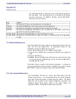
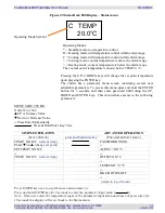
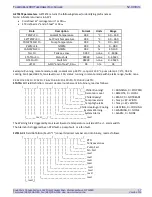
Status Menu: The status menu displays the chiller operating status
and coolant temperature. The chiller operating mode is shown in the
display’s first character: (See Figure 4)
ALRM +/-: Alarm width, the acceptable coolant operating
temperature range around set-point before an alarm is communicated
via USB. For example, if set to 5°C with a 20°C set-point, an alarm
will trigger if the coolant temperature rises above 25°C or falls below
15°C.
OFFSET: This parameter raises or lowers the chiller temperature
reading to match a user’s external temperature sensor. Enter the
difference between the external sensor and the display. For example,
if the user has a temperature sensor reading of 22 °C when the chiller
display shows 20°C, entering 22°C – 20°C = 2°C will cause the
chiller to shift its temperature calibration scale up 2°C to match the
external sensor.
TEMPUNIT: Sets temperature units in degrees Celsius or
Fahrenheit.
BKLIGHT: Setting this parameter to ON turns on the display back-
light; setting this parameter to OFF turns off the display back-light.
5.3
A
LARMS
Alarms are displayed on the front screen, and communicated through
USB interface.
A list of system failure modes can be found in Section 6. In the event
of a system failure, the alarm type will be shown on the front display.
5.4
D
RAIN
P
ROCEDURE
1.
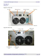
Connect one end of the drain hose with the Colder Products
PLCD2204 coupling insert provided with the ThermoRack 800
into the front drain fitting (see figure 3A) and place the other end
into a container with at least a 3 liter capacity.
2.
Remove the tank cap.
3.
Allow the tank to drain.
4.
Disconnect coolant lines from the equipment being cooled and
place the lines in a bucket.
5.
Turn on the ThermoRack for 15-20 seconds, and then turn off.
6.
A small amount of coolant will remain in the bottom of the tank.
Removing this remainder (not necessary to ship the unit) requires
lifting the rear of the chassis.
7.
Remove the drain hose.
8.
Replace the tank cap.
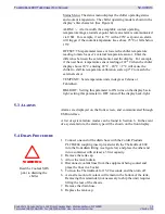
WARNING
Read the Coolant SDS
prior to draining the
chiller


