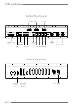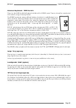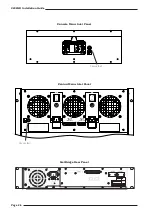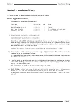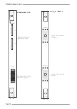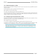
I/O – MicAmp Card (SSL ref. 908)
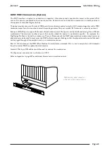
Each MicAmp Input Card contains 12 Microphone circuits. The inputs are accessed via a Varicon (aka. EDAC or Elco) 56-
way female connector.
The split outputs are accessed via two 25-pin D-type female connectors.
Refer to Appendix C for the connector pinouts.
SSL is able to supply mating connectors if requested, (at additional cost).
If more than one micamp card is fitted then the card furthest to the right will have the lowest input number and the channel
numbers will increment by 12 as each card is added. Any cards added subsequently, should be placed to the left of any
existing cards otherwise the channel numbering will be altered.
I/O – Analogue input/output Card (SSL ref. 904)
The Analogue Card provides 24 circuits of electronically balanced input and output. These circuits are accessed via Canon
DL 96 way female connectors; mating connectors are available to order
Refer to Appendix C for the connector pinouts.
As is the case for the MicAmp, cards added subsequently should be placed to the left of existing cards.
The default line-up level for analogue I/O is 0dBFS = +18dBu. This level may be globally altered and can range from +9dBu
to +24dBu. The value can be adjusted from a setup screen to match the standard operating level for the facility.
When assigning analogue output channels as insert sends, the routing system will automatically assign the same input
channel number as the corresponding return. It is therefore necessary to physically wire outboard equipment so that
circuit allocation follows this arrangement.
Installation Wiring
Section 5
Page 31

