Soundscape Mixpander
Page 45 of 59
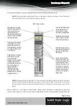
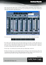
The screenshot below is used to describe the structure of mixer columns 1 to 32.
NOTE:
The
signal
path
is
always
from
the
top
to
the
bottom
of
the
mixer
column,
so
that
the
order
of
the
mixer
elements
is
an
exact
reflection
of
the
signal
path.
NOTE:
The
input
elements
of
the
first
32
mixer
columns
are
muted
by
default,
except
for
columns
1
and
13
(the
first
digital
and
analogue
stereo
pairs).
If
you
want
to
hear
sound
sources
connected
to
the
other
inputs,
please
click
the
relevant
Mute
buttons
to
unmute
the
corresponding
mixer
column
inputs.
Mixer columns 1 to 32 feature Track Inserts. These mixer elements are designed to send and
receive audio data to and from your audio applications via the corresponding streams (they are
Mixer column number.
Input element.. The input
element’s label reflects its
current assignment to a
physical input of the
XLogic Alpha-Link (AES 9-
10 for an Alpha-Link MADI
SX in this example).
Track Insert. This element
can be linked to a record
track/mixer column in an
audio application, via input
and output streams 9 and
10 in this case.
Output element.. Features
a level fader, a pan pot
and Center button
(between the pan readout
and dB scale), Solo (S)
and Mute (M) buttons and
Solo Group (SG) and
Fader Group (FG)
selection boxes. The
output element’s label
indicates that it is currently
assigned to Bus 1-2.
Multi-EQ module. Double-
click this mixer element to
open the corresponding
EQ window.
Input element Mute button.
The input signal to this
mixer column is muted
(the button is highlighted).
Sends. These elements
feature a level slider, pan
pot and mute button. They
route the signal to mixer
columns 34 via bus 11-12,,
35 via bus 13-14 and 36
via bus 15-16. (The input
elements of these mixer
columns are assigned to
these buses).
Peakmeter (it will indicate
when a signal is received
at the input just above it).


