background image

Tutorial

8

THE BUS+ User Guide

Tutorial

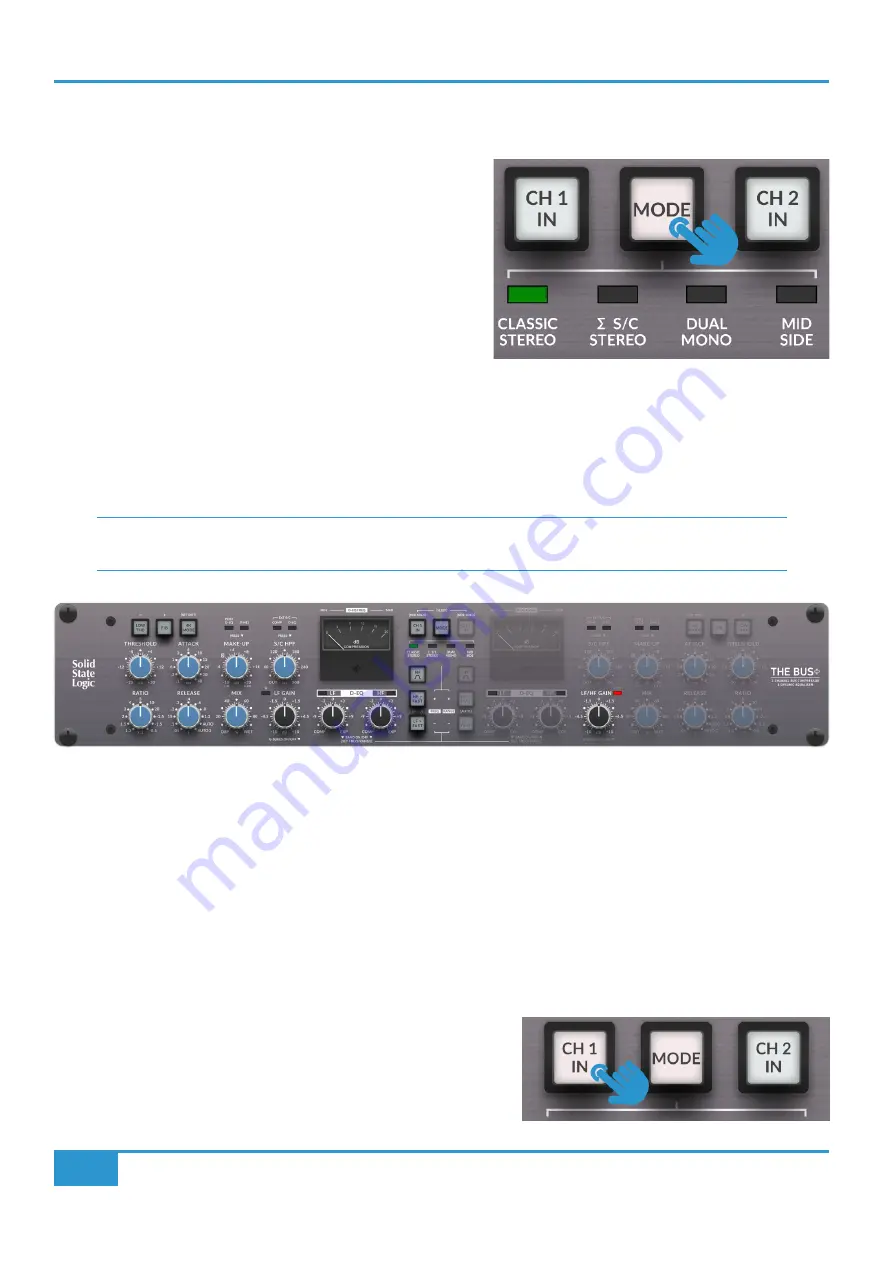
MODE Selection

The Bus+ has four different modes of operation to choose from. 
Pressing the 

MODE

 switch will move you through the options.

CLASSIC STEREO

 - This is the classic mode of operation for the SSL 

Bus Compressor. Designed to be used on stereo sources, the controls 
on the left-hand side of the unit determine the settings of both left 
and right channels. The right hand controls are disabled and have no 
function associated to them in this mode (with the exception of the 

LF

/

HF GAIN

 D-EQ control).


S/C STEREO

 - An alternative stereo mode of operation. The controls on the left-hand side of the unit determine the settings 

of both left and right channels. In this mode, the left and right side-chain signals are summed together, as opposed to being 
individually rectified. The effect of this is that the Bus Compressor becomes 'more sensitive' towards mono content in a stereo 
source - typically instruments like kick, snare, bass. Have a go at switching between 

CLASSIC STEREO 

and 


S/C STEREO 

to 

see which you prefer on the material you're compressing.

A short press and hold on the MODE switch allows you to 'go backwards' through the modes, useful for A/B'ing 

between two adjacent options.

DUAL MONO

 - This mode configures the Bus Compressor as two entirely independent mono processing engines. The controls 

on the left-hand side determine the settings for channel 1 and the right-hand side controls determine the settings for channel 2.

MID SIDE

 - The Bus+ has built-in Mid-Side encode-decode circuitry that allows the left-hand side of the unit to process the 'Mid' 

signal and the right side of the unit to process the 'Side' signal. This mode is a great tool for Mastering engineers.

CH 1 IN and CH 2 IN Switches

These switches allow you to bypass all Bus Compressor and D-EQ 
processing. In stereo modes, the 

CH 2

 switch is disabled as 

CH 1

 controls 

both left and right channels.

In CLASSIC STEREO or �S/C STEREO, the right-hand side LF/HF GAIN control functions as the 

High Frequency

 Gain control 

for both left and right (linked) channels. This is indicated by the red LED that accompanies the control (see illustration above). 

In DUAL MONO or MID SIDE mode, the right-hand side LF/HF GAIN control functions as the 

Low Frequency

 Gain control for 

Channel 2. This means that HF GAIN is only accessible in CLASSIC STEREO or �S/C STEREO modes.

Summary of Contents for THE BUS+

Page 1: ...THE BUS www solidstatelogic com THE BUS User Guide ...

Page 2: ...e reproduced in any form or by any means whether mechanical or electronic without the written permission of Solid State Logic Begbroke OX5 1RU England As research and development is a continual process Solid State Logic reserves the right to change the features and specifications described herein without notice or obligation Solid State Logic cannot be held responsible for any loss or damage arisi...

Page 3: ...Dynamic Equaliser D EQ 14 Settings 20 Brightness 20 Relay Feedback 20 Mix Control Mode Classic or Parallel 20 Operating Level Input Gain Trim 21 Auto Sleep 21 Deep Sleep Waking Up 22 Input Stage Low Pass Filter 22 Side Solo Mode 23 Right Hand Side Meter On Off Stereo Modes 23 Factory Reset 24 Deep Factory Reset 24 Code Break Master Game 25 The Prize Unlocked Transient Expander Feature 27 Bus Compr...

Page 4: ... this has the obvious advantage of making recalls easier but there s actually more cleverness going on here Stepped pots on their own may make recalls easier but simply using them instead of continuous pots doesn t lead to any technical advantage per se as they are still subject to mechanical tolerances that can compromise stereo matching and the overall analogue performance So we went even furthe...

Page 5: ... grunge to the mix Negative Ratios for creative pumping effects and control of particularly loud signals New Attack and Release time constant options more flexibility to shape the Bus Compressor including the new Auto 2 setting Precision MDAC controlled MAKE UP Gain with two ranges available Coarse 1 dB steps or Fine 0 5 dB steps Variable side chain High Pass Filter control up to 300 Hz in 10 Hz s...

Page 6: ...2U 19 rackmount piece of equipment designed to sit in the racking of a producer s desk or similar It is recommended that ventilation space is left above and below the unit so any heat generated by The Bus can naturally disperse The sides of The Bus chassis have cut outs that should under no circumstances be blocked or covered Always allow The Bus to cool down before handling Safety Notices Please ...

Page 7: ...he high frequency band filter from shelving to bell BUS COMPRESSOR SWITCHES Special Bus Compressor features unique to The Bus LOW THD F B 4K MODE D EQ CONTROLS BLACK KNOBS 2 Band Dynamic Equaliser Controls for Compression Expansion and LF HF Gain BUS COMPRESSOR CONTROLS BLUE KNOBS Bus Compressor side chain Mix and Gain Make up controls EXT S C IN EXTERNAL SIDE CHAIN INPUTS Connect external sources...

Page 8: ...essing A short press and hold on the MODE switch allows you to go backwards through the modes useful for A B ing between two adjacent options DUAL MONO This mode configures the Bus Compressor as two entirely independent mono processing engines The controls on the left hand side determine the settings for channel 1 and the right hand side controls determine the settings for channel 2 MID SIDE The B...

Page 9: ...n your preference By default the Side signal is presented on both left and right outputs in phase when solo d This can be changed in the Settings menu to be presented after passing through the M S decoder i e Side signal out of phase on right output Sleep Mode You can put the unit into SLEEP mode by pressing and holding both the CH 1 IN and CH 2 IN switches together for 2 seconds or until they sta...

Page 10: ...UTO is the same automatic option as found on all other SSL Bus Compressor suitable for complex material as the release circuitry has a two stage release 100 ms short 12 seconds long This means that louder elements of the signal are released quickly and quieter elements more slowly AUTO 2 50 ms short 6 seconds long is a new option providing a slightly more active automatic setting MAKE UP A gain ma...

Page 11: ...nter clockwise position Please note that MIX only applies to the Bus Compressor part of The Bus D EQ is unaffected by the MIX control LOW THD Most compressors by their nature start distorting low frequencies before high ones particularly when set for fast release times Sometimes this forms part of the desirable analogue character but other times it is counter productive Pressing the LOW THD switch...

Page 12: ... console was implemented and secondly it introduces a variable amount of harmonic distortion via the VCA These two factors combine to allow for a more coloured sound Adjusting the distortion amount you ll find there s a certain sweet spot depending on your mix level in which your material will become more cohesive thanks to the added thickness Since distortion is not achieved by means of overloadi...

Page 13: ...nput External S C Input For LF and HF Ext S C Input Bus Comp Ext S C Input D EQ Ext S C Input Both Ext S C Input Off External S C Input For HF Only External S C Input For LF Only Whilst keeping the S C HPF control held down press the LF control This will return the LF band to being sourced from the internal side chain whilst the HF band remains triggered from the external side chain input The HF D...

Page 14: ...reative uses beyond this particularly using the expansion to enhance source material D EQ CONTROLS The D EQ is a 2 band LF and HF dynamic EQ with both engines able to be turned on off bypassed individually The default frequency of the LF Shelf is 60 Hz The default frequency of the HF Shelf is 6 kHz When the HF Shelf is changed to a Bell using the HF BELL switch the default frequency is 4 kHz All o...

Page 15: ...hird AUTO setting to be chosen Switch lights magenta to indicate this Time constants for AUTO are 10 ms attack AUTO release LF HF GAIN The LF GAIN control left hand side of the unit provides 10 dB of boost or cut to the low frequency band of the D EQ This is control over the static band of the EQ The LF GAIN can be used to apply a boost cut of regular EQ to compensate for any dynamic EQ activity F...

Page 16: ...octave and an amount of overshoot undershoot is added to the shelving filters above the frequency cut off point similar to that found on G Series SSL EQs This can provide a slightly different sonic character to the EQ which we have found to be pleasant on sources like drum busses Please note this is only available for the LF GAIN band not the HF band stereo modes only G Series Mode Graph Undershoo...

Page 17: ...ressing the HF FAST switch will move the frequency point upwards whilst pressing the LF FAST button will move it downwards The left hand side meter needle shows the current setting Press and hold the LF or HF control if you re adjusting that band or the MODE switch to exit Adjusting the Range Presuming you are have already entered the setup mode by pressing and holding the LF or HF control Pressin...

Page 18: ...ch needle position corresponds to The default frequency of the LF Shelf is 60 Hz The default frequency of the HF Shelf is 6 kHz The default frequency of the HF Bell is 4 kHz LF HF HF BELL The HF BELL filter is a Proportional Q design reaching a Q value of 1 87 at maximum boost cut 10dB The Q is 1 04 at 5 dB ...

Page 19: ...3 different ranges values that can be chosen from The minimum is a range of 0 5 dB and the maximum if 15 dB Between 0 5 and 8 dB the steps are in 0 5 dB and between 8 and 15 dB the steps are in 1 dB Usefully the markings already on the meter correspond directly to the equivalent Range values For example the needle is showing that the Range is set to 4 dB here ...

Page 20: ...ay feedback is disabled Mix Control Mode Classic or Parallel The MIX control can work in two different ways Classic mode cross fades between dry and wet signals whilst Parallel mode keeps the dry signal at 100 and brings up the wet fader as the control is rotated towards the fully clockwise WET position The Parallel mode allows for NY style parallel compression very easily To switch between Classi...

Page 21: ...t mixes effectively altering the threshold range from 20 20 dB to 25 15 dB Auto Sleep In addition to putting The Bus into Sleep mode manually by pressing CH 1 IN and CH 2 IN switches together in normal operation the unit can enter Sleep mode automatically after a specified amount of time of inactivity Inactivity can mean either the pots and or switches have not been operated It can also mean there...

Page 22: ...nput Stage Low Pass Filter Some DACs or Audio Interfaces depending on the implementation can exhibit excessive out of band noise Whilst you won t directly hear it it may cause unwanted triggering of Bus Compressor and D EQ side chains When that happens you ll notice the gain reduction meter being displaced or the D EQ indicators lit with no audio being played It may also cause increased noise floo...

Page 23: ...the M S decoder Right Hand Side Meter On Off Stereo Modes By default in normal operation if The Bus is in Classic Stereo or S C Stereo modes then the right hand side gain reduction meter is disabled However this can be changed so that both meters light up and operate in these stereo modes You toggle the right hand side meter to be on off in stereo modes pressing the CH 1 IN switch If the CH 1 IN s...

Page 24: ...Autosleep On Off default Off Autosleep timeout default 20 min LPF default disabled Parallel Mix mode default disabled Side Solo mode default in phase Right hand side Meter On Off in Stereo Mode default Off Deep Factory Reset The Bus offers a Deep Factory Reset which is the same as the standard Factory Reset described above but it also resets the Transient Expander to be unavailable locked out To u...

Page 25: ...rounds to guess correctly i e break the code The number of guessing rounds you have remaining is indicated by the position of the left hand side meter needle Entering The Game Press and hold the left hand side CH 1 IN HF BELL HF FAST and LF FAST switches whilst The Bus is powering on Starting The Game The MODE switch will be pulsing red and the front panel LEDs swiping left and right like a famili...

Page 26: ... a correct colour AND it is in the correct position For example 2 Red LEDs would mean you have correctly guessed the colour of 2 of the 4 switches but they are both in the wrong position Another example would be 1 Green LED and 3 Red LEDs meaning that one of the colours you have picked is correct both for the colour and the position and the other 3 colours are correct but all in the wrong position...

Page 27: ... run out then The Bus will flash all front panel LEDs RED but do not fear simply press the MODE key twice to have another go Exiting The Game Press and hold the right hand side LOW THD switch to reboot the unit into normal operation The Prize Unlocked Transient Expander Feature Congratulations on breaking the code As a reward you have unlocked the Transient Expander feature Returning The Bus to no...

Page 28: ... should use the front panel flat head screwdriver adjustment to move the needles closer to their 0 positions if necessary 4 Mark Calibration When you are happy with the 0 mark calibration press the left hand side side F B switch to move onto the calibration for the 4 mark the meter needles move towards 4 Next use the left hand side LF FAST HF FAST switches to move the left hand side needle as clos...

Page 29: ...k the following LEDs light red to indicate which mark is currently being calibrated EXT S C D EQ Left LED 0 dB mark mechanical alignment Classic Stereo 4 dB mark calibration Sum SC Stereo 8 dB mark calibration Dual Mono 12 dB mark calibration Mid Side 16 dB mark calibration EXT S C Comp Right 20 dB mark calibration Saving The Calibration Important To save the current calibration and exit press and...

Page 30: ...D 2nd digit FB Left FW UID 3rd digit 4K MODE Left FW UID 4th digit 4K MODE Right FW UID 5th digit FB Right Main board HW revision LF FAST Left Front panel HW revision LF FAST Right Once the required digit is selected the information is obtained by counting the number of indicator LEDs lit up GREEN E g if the current digit is 3 this will be indicated by POST D EQ MAKEUP FINE EXT S C COMP LEDs all l...

Page 31: ...ssible to test the correct operation of the potentiometers A position change on any of the pots will trigger the relay to click as a confirmation feedback To exit press and hold the MODE key and the unit will power cycle Power Check The Bus has a built in system to self check most of the internal power supply rails If a fault is detected at any time all the rails are shutdown for safety and a user...

Page 32: ...rement Value Conditions Input Impedance 10 kΩ Output Impedance 60 Ω Maximum Input Output Level 27 5 dBu Operating Level Modes 0 dB 5 dB 1 THD Frequency Response 0 025 dB 1 Hz 200 kHz Bypassed 20 Hz to 20 kHz Bypassed 3 dB low cut off Bypassed 3 dB high cut off 0 01 dB 2 Hz 180 kHz Compressor In 20 Hz to 20 kHz Compressor In 3 dB low cut off Compressor In 3 dB high cut off THD N 95 dB 0 0017 typica...

Page 33: ...er LF maximum frequency HF minimum frequency Unless otherwise quoted all figures have a tolerance of 0 5dB or 5 Audio Performance Measurement Value Conditions Frequency Response 20 Hz 20 kHz 0 05 dB 2 Hz 200 kHz LF In 20 Hz to 20 kHz LF In 3 dB low cut off LF In 3 dB high cut off 0 05 dB 2 Hz 200 kHz HF In 20 Hz to 20 kHz HF In 3 dB low cut off HF In 3 dB high cut off THD N 88 dB 0 004 typical 81 ...

Page 34: ... Width 480 mm 19 inches Height 88 9 mm 3 5 inches 2 RU Depth 303 mm 11 9 inches chassis only 328 mm 12 9 inches total including front panel controls Weight 5 92 kg 13 1 lbs Boxed Dimensions 550mm x 470mm x 225mm 21 7 x 18 5 x 8 9 Boxed Weight 8 68 kg 19 14 lbs Connectors Inputs Female XLR x2 External Inputs Female XLR x2 Outputs Male XLR x2 External Sends Male XLR x2 ...

Page 35: ...y Actionable Switch Subsequent switches always action in response to first directly actionable switch Stereo Linking Possible KEY PUSH FOR FINE MDAC 10 to 20 5 to 10 LPF 26 kHz 26 kHz 26 kHz 26 kHz EXT S C IN 2 ENTER SETTTINGS MENU TO CHANGE EXT LF LF GAIN LF COMP EXP FAST FREQ RANGE FAST FREQ RANGE BELL PUSH ON OFF PUSH ON OFF EXT HF EXT LF LF GAIN LF COMP EXP FAST FREQ RANGE HF COMP EXP FAST FRE...

Page 36: ..._______________________________ Notes _________________________________________ _____________________________________________________________ _________________________________________ _____________________________________________________________ _____________________________________________________________ _____________________________________________________________ ______________________________...

Page 37: ...ower on the unit whilst holding the MODE key down to enter SETTINGS mode Press and hold the right hand side HF BELL key for 2 seconds to toggle Transient Expander Mode on off If HF BELL is lit GREEN then Transient Expander Mode is enabled If HF BELL is dimly lit white Transient Expander mode is disabled See the bottom of Page 27 for more details on this mode Press and hold the MODE key whilst The ...

Page 38: ...s Rack shelves are recommended When rack mounting allow a 1U gap above and below the unit for cooling Ensure that no strain is placed on any cables connected to this apparatus Ensure that all such cables are not placed where they can be stepped on pulled or tripped over Power Safety Bus is supplied with a mains lead however if you wish to use a mains cables of your choice it must comply with the f...

Page 39: ... and the environment For more information about where you can drop off your waste equipment for recycling please contact your local city office your household waste disposal service or where you purchased the product FCC Certification This device complies with part 15 of the FCC Rules Operation is subject to the following two conditions 1 This device may not cause harmful interference and 2 this d...

Page 40: ...t output ports are screened cable ports and any connections to them should be made using braid screened cable and metal connector shells in order to provide a low impedance connection between the cable screen and the console Safety EN IEC 62368 1 2020 A11 2020 BS EN IEC 62368 1 2020 A11 2020 UL 62368 1 3rd Ed 2019 CAN CSA C22 2 No 62368 1 19 3rd Edition This equipment is not suitable for use in lo...

Page 41: ...THE BUS www solidstatelogic com ...

Reviews: