Page F-2
X-Rack Owner’s Manual
F.3.2 Monitor Section
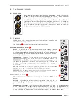
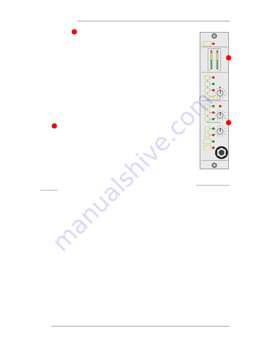
The Monitor Section enables the Mix and Record busses or a stereo external input to
be monitored, the source to monitor being set by either the ‘MIX’, ‘REC’ or ‘EXT’
switches either seperately or together, allowing great flexibility in recording and
montitoring signals. The ‘EXT’ input would normally be playback from the main
recorder or DAW. The selected monitor signals can be routed back to the Mix output
using the MON switch in the Mix Section, allowing composite mixes to be easily
recorded back to the master recorder or DAW ADC.
If one of the ‘SOLO’ switches on any other X-Rack modules is active, the ‘SOLO’
LED will illuminate and the AFL bus will be switched to the monitor output in place
of the selected signal. The level of the AFL signal can be adjusted with the ‘AFL’
control.
The overall monitor level is set by the ‘LEVEL’ control and the ‘MONO’ switch
allows quick mono compatibility checking. The ‘DIM’ and ‘CUT’ switches provide
either partial (between –3 and –30dB) or full attenuation of the monitored signal as
required.
Metering of the selected source (or sources) is provided by the stereo bargraph
meter
which measures the signal level immediately prior to the ‘LEVEL’ control.
Two sets of stereo loudspeaker outputs plus a headphone amplifier are provided.
The headphone socket is driven by a fixed gain amplifier immediately post the
‘LEVEL’ control and is un-affected by the loudspeaker ‘ALT’ switch.
F.3.3 Expansion
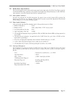
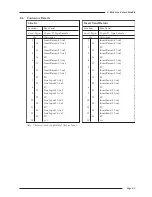
Each of the three X-Rack busses (Mix, Record and Solo/AFL) are accessible
externally through the ‘MIX BUS LINK’ connector on the rear of the X-Rack.
Additional X-Racks can be connected via this connector, allowing additional inputs
to be mixed together and feed a single Master module. The pinout for this connector
is detailed in
Section 5.2
of the X-Rack Owner’s Manual; if the connector listing is not present in your
manual, a more recent copy may be downloaded from the Solid State Logic website (
http://solid-state-
logic.com
).
Note. Only one XR622 master module is required per system – connecting two or more X-Rack units fitted with XR622
modules together will cause serious gain errors and distortion (though it will not damage the system electronics).
F.3.4 Configuration
Dim Level
The attenation applied to the monitor signal when the ‘DIM’ switch is active is set by the Total Recall
processor. The default level is –15dB, it can be adjusted as follows:
• Press and hold
SETUP/MIDI
until the
SETUP/MIDI
LED flashes.
• Use the D-Pot to select ‘
d1
’ (DIM Level). Press the D-Pot to select this option.
• Use the D-Pot to set the required level (between –3dB and –30dB).
• Press the D-Pot once more to set the selected value and return to the setup menu or press and hold
SETUP/MIDI
until the
SETUP/MIDI
LED stops flashing to return to normal operation.
MIDI Remote
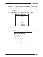
Controlling the ‘soft’ controls on the XR622 Master module via MIDI will require MIDI controls to be
mapped onto the required Master module functions. This is accomplished as follows:
• Press and hold
SETUP/MIDI
until the
SETUP/MIDI
LED flashes.
• Use the D-Pot to select ‘
m1
’ (MIDI Setup). Press the D-Pot to select the MIDI Setup menu.
• Use the D-Pot to select ‘
ck
’ (MIDI Channel). Press the D-Pot to select this option.
• Use the D-Pot to set the MIDI Channel to listen to (‘
01
’ to ‘
16
’ or ‘
al
’ for ‘all’). Press the D-Pot to leave
this option.
3
2
SEL
XR622
MIX LEVEL
AFL
LEVEL
MIX
REC
MONITOR
SUM
MON
SUM
INS
INS
REC
MIX
EXT
ALT
MONO
SOLO
DIM
CUT
MONITOR
0
3
6
9
12
15
18
24
30
36
42
48
2
3
Summary of Contents for X-Logic
Page 1: ...X Rack Owner s Manual ...
Page 2: ......
Page 24: ...Page 20 X Rack Owner s Manual Notes ...
Page 32: ...Page B 2 X Rack Owner s Manual ...
Page 38: ...Page B 8 X Rack Owner s Manual ...


