background image

Super Analogue Channel

Owner’s Manual

Summary of Contents for XLogic Super Analogue

Page 1: ...Super Analogue Channel Owner s Manual ...

Page 2: ......

Page 3: ...Solid State Logic Super Analogue Outboard Owner s Manual 82S6XL040D S U P E R A N A L O G U E C H A N N E L ...

Page 4: ...USA 1 1 323 549 9090 3 55 14 Sendagaya Shibuya Ku Tokyo 151 0051 Japan 81 0 3 5474 1144 7 bis rue de la Victoire le Blanc Mesnil Paris 93150 France 33 0 1 48 67 84 85 Via Timavo 34 20124 Milano Italy 39 0 39 2328 094 Visit SSL at URL http www solid state logic com Solid State Logic All Rights reserved under International and Pan American Copyright Conventions Solid State Logic SSL and XLogic are t...

Page 5: ... 4 0 Operation 8 Input Section 8 Dynamics Section 9 Filter Section 10 Equaliser Section 11 Output Section 11 5 0 Signal Routing 12 Block Diagram 12 Signal Routing 13 Appendices A Internal Links and Fuses 14 B Connector Details 15 C Electronic Specification 16 D Calibration Information 21 E Physical Specification 24 F Environmental Specification 24 Page 1 ...

Page 6: ... 1 0 COMPRESSOR 10 1 20 14 10 6 3 RELEASE 1 4 0 20 RATIO 1 DYN IN KEY LINK PRE EQ PK FAST ATT dB 72 INP B INST GAIN 12 6 0 12 24 24 18 MTR INPUT 7 KHz 1 5 22 2 15 GAIN BELL 20 20 3 5 DYNAMICS FAST ATT GATE 30 Hz 500 20 60 100 300 RANGE 0 40 HPF IN 66 60 54 48 42 36 30 24 18 12 6 INPUT B INSTRUMENT INPUT GAIN OUTPUT Ø ADC LOCK POWER THRESHOLD 4 10 XLSUPER ANALOGUE C H A N N E L Solid State Logic og...

Page 7: ...ur local distributor who will arrange for it to be shipped to Solid State Logic for repair All units should be shipped to Solid State Logic in their original packaging Solid State Logic can not be held responsible for any damage caused by shipping units in other packaging In such cases Solid State Logic will return the unit in a suitable box which you will be charged for Please do not send manuals...

Page 8: ... voltage range is set correctly before applying power Always isolate the mains supply before changing the input range setting If it is ever necessary to replace a blown mains fuse then always use the correct rating and type of replacement If a correctly rated fuse continues to blow then a fault exists and the cause should be investigated or the unit returned to Solid State Logic for repair replace...

Page 9: ...in the product specification In certain countries this function is supplied by use of a fused plug CE Certification Note that the majority of cables supplied with SSL equipment are fitted with ferrite rings at each end This is to comply with current European CE regulations and these ferrites should not be removed If any of the unit metalwork is modified in any way this may the adversely affect the...

Page 10: ...V Setting Use for 90 105V 120V Setting Use for 105 125V 230V Setting Do not use 240V Setting Use for 220 240V Mains Input Module Mains Input Programming PCB These diagrams show the PCB arrangements for the different voltage settings Note that where the mains voltage is a nominal 230V the 240V Setting should be used not the 230V Setting ...

Page 11: ... ears of early XLogic Channel units are not capable of supporting the full weight of the unit Therefore if the unit is to be rack mounted it must either be mounted on suitable rack shelves or be fitted with a pair of support brackets to reinforce the rack ears do not rely on just the basic front panel for rack mounting the unit Later XLogic Channel units incorporate reinforcement brackets into the...

Page 12: ...pped INPUT GAIN control has a gain range of 6dB to 72dB in 6dB steps HI Z Increases the input impedance of the microphone input inputs A or B from 1 2kΩ to 8 45kΩ This allows the connection of line level signals to the channel input if required and provides an alternative input impedance for some dynamic microphones PAD This switch reduces the signal level by 18dB Setting the gain to 18dB and sele...

Page 13: ... a keying signal from one section to trigger the other The easiest way to do this is by patching from the output of the source channel into the Key input of the destination channel and selecting KEY see above on this channel 4 3 Compressor Limiter RATIO When turned to 1 1 the Compressor Limiter section is inactive Turning the control clockwise increases the compression ratio to give a true limiter...

Page 14: ...es Variable from 0 to 4 seconds The green LEDs in the display section indicate Expander Gate activity the amount of gain reduction Note that when the Dynamics section is not in circuit its sidechain input is also bypassed 4 5 Filters Section This section comprises a four band parametric equaliser plus high and low pass filters The EQ and filters can be routed separately to different audio paths wi...

Page 15: ...ously variable Q 0 7 2 5 LMF Section Centre frequency 200Hz to 2 5kHz gain 20dB continuously variable Q 0 7 2 5 Normally at any Q setting the bandwidth of the HMF and LMF sections varies with gain whereby an increase in boost or cut increases the selectivity of the EQ This type of EQ can sound effective when used at moderate settings the gentle Q curve lends itself to the application of overall EQ...

Page 16: ... A INPUT B INSTRUMENT Ø KEY INPUT DYN S C EQ F EQ F DYN SCH DYN SCH KEY F DYN S C INPUT PRE EQ LINK Stereo Jack DYN LINK INP B OUTPUT GAIN 20dB OUTPUT 12 6 0 12 24 24 18 MTR INPUT INST XLogic Channel Owner s Manual Page 12 XLogic Channel Block Diagram ...

Page 17: ...ear of the unit by selecting KEY The table below shows the sidechain source and processing for the various combinations of DYN S CH switches Switch 1 Switch 2 KEY Input EQ to DYN S C KEY Input Equaliser Filters to DYN S C KEY Input Filters EQ to DYN S C Filters to DYN S C KEY Input Equaliser Filters Side chain processing order Switch 1 Switch 2 Side chain source Dynamics Input EQ to DYN S C Dynami...

Page 18: ...es should only be changed by suitably experienced staff They are listed below Fuses 629610X2 Power Regulator Card 48V FS1 500mA wire ended SSL part No 35F5E250 Fuses 629601X1 Main Card 18V FS1 3 amp wire ended SSL part No 35F5E330 15V FS2 3 amp wire ended SSL part No 35F5E330 15V FS3 3 amp wire ended SSL part No 35F5E330 18V FS4 3 amp wire ended SSL part No 35F5E330 5V FS5 3 amp wire ended SSL par...

Page 19: ...iption 1 Chassis 2 Audio ve 3 Audio ve Instrument Input Location Front Panel Conn Type Mono 1 4 Jack Socket Pin Description Guitar Input Chassis Tip Sleeve Dynamics Link Location Rear Panel Conn Type Stereo 1 4 Jack Socket Pin Description Link Bus Link Bus 0V Tip Ring Sleeve Note that tip and ring are linked to allow use of mono jacks ...

Page 20: ...surements are specified as 22Hz to 22kHz band limited RMS and are expressed in units of dBu All distortion measurements are specified with a 36dB Octave low pass filter at 80kHz and are expressed as a percentage The onset of clipping for headroom measurements should be taken as 1 THD Unless otherwise quoted all figures have a tolerance of 0 5dB or 5 Channel Microphone Amplifier Measurement Conditi...

Page 21: ...3 at 1kHz 10dBu applied 30dB gain 0 005 at 10kHz Frequency Response 0 05dB 0 1dB from 20Hz to 20kHz 3dB at 200kHz Equivalent Input Noise 70dBu at 40dB gain Input terminated with 150Ω 89dBu at 20dB gain Channel Output Output is fully balanced and floating and incorporates SSL s cable compensating output design allowing it to drive long cable runs without degrading the frequency response Gain Contin...

Page 22: ...the selectivity of the EQ as the gain is increased With the E switch IN the frequency bandwidth is constant at all gains At full boost or cut both are identical HF Band controls Frequency Variable from 1 5kHz to 22kHz Gain Variable between 20dB Q 2 5 on BELL setting HMF Band controls Frequency Variable from 600Hz to 7kHz Gain Variable by 20dB Q Variable from 0 5 to 2 5 may also vary with gain LMF ...

Page 23: ...0 10 0 5 0 0 0 5 0 10 0 15 0 20 0 25 0 Amplitude dBr v Frequency Hz Channel Equaliser Curves G type E type Both 0 0 25 0 25 0 20 100 1k 10k 100k 20 0 15 0 10 0 5 0 5 0 10 0 15 0 20 0 Amplitude dBr v Frequency Hz Channel Equaliser Curves G type E type ...

Page 24: ...uto sensing switchable to 150µs Hold Time Variable from 0 to 4 seconds Release Time Variable from 0 1 to 4 seconds The side chain signal can be sourced either from the signal feeding the dynamic or the external Key input Filters and or Equaliser can be inserted in the sidechain LED meters independently indicate amount of compression and expansion Measurement Conditions Signal applied to Input A ou...

Page 25: ...p Set the Input Gain to 36dB and the Output Gain to indent 0dB CMRR Trim Adjustment On the 629602 card adjust VR22 for minimum level normally 40dBu Output Stage Equipment Required Calibrated audio oscillator and audio level meter Test Signal 1kHz sinewave 6dBu Input and Output Oscillator to Input A or B and Output to the audio level meter Unit Setup 1 Set the Input Gain to 6dB and the Output Gain ...

Page 26: ...djust HF Frequency to find the maximum level on the audio level meter 2 On the 629603 upper card adjust VR26 for 20dBu 0 25dB 3 Reset HF Gain to its centre indent position de select HF BELL and re check the audio level meter for 0dBu HMF EQ Maximum Gain Adjustment 1 Set HMF Gain to maximum and HMF Q fully anti clockwise Set the audio oscillator for 3kHz and adjust HMF Frequency to find the maximum...

Page 27: ...A using clip probes and a suitable lead 3 Adjust the offset trim VR23 to null the control voltage feedthrough seen at the output typically less than 65dBu Sidechain Offset Adjustment 1 Connect the level meter to the Output and set the oscillator level for 28dBu 2 Turn preset VR28 fully anti clockwise 3 Measure the DC voltage at test point TP4 relative to 0VA use TP6 and adjust VR25 for 0V 10mV Com...

Page 28: ...g 14 pounds All weights and dimensions are approximate Appendix F Environmental Specification Temperature Operating 5 to 30 Deg C Non operating 20 to 50 Deg C Max Gradient 15 Deg C Hour Relative Humidity Operating 20 to 80 Non operating 5 to 90 Max wet bulb 29 Deg C non condensing Vibration Operating 0 2 G 3 100Hz Non operating power off 0 4 G 3 100Hz Shock Operating 2 G 10mSec Max Non operating 1...

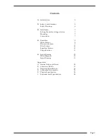
Page 29: ...Notes Appendix Page 25 ...

Page 30: ...XLogic Channel Owner s Manual Page 26 ...

Reviews: