background image

4.

Operation

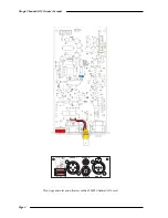
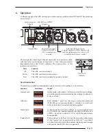
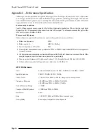
On the rear panel of the ADC card are four sockets and one multi-position DIP switch. Their functions
are as follows:

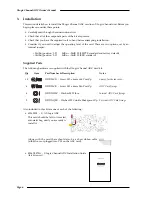
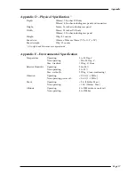
The front panel of the XLogic Channel unit carries no controls associated
with the ADC card although it does have a ‘Lock’ indicator, located
immediately below the ‘Power’ indicator. The various states of this
indicator are as follows:

State

Function

Off

The ADC card is not locked.

Yellow

The ADC card is set to internal sync.

Red

The ADC card is set to external sync and is locked.
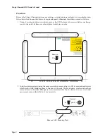
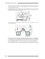
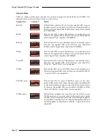
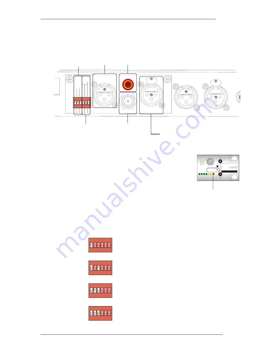
Synchronisation

There are four possible synchronisation options, selected with switches 1 to 3 as follows:

Function

Switch(es)

Detail

Internal sync

In this mode, with switch 1 ‘off’ (down), the ADC card will free-
run at the sample rate determined by the setting of switches 4 to
6 (see over leaf).

AES sync

With switches 1 and 3 set this way, an external un-balanced
(75Ω) AES sync source may be used – switches 4 to 6 will need
to be set to match the nominal rate being applied.

Word Clock

In this mode the ADC card will lock to an external TTL level
word clock at any nominal sample rate between 44.1kHz and
192kHz – again, set switches 4 to 6 to match the nominal rate
being applied.

‘Super Clock’

With switches 1 to 3 all set ‘on’ (up), the card will synchronise to
a 256x ‘Super Clock’ as provided from ProTools™ – switches 4
to 6 should be set to match the nominal rate being used (sample
rates greater than 96kHz are 

not 

supported).

ON

1 2 3 4 5 6

ON

1 2 3 4 5 6

ON

1 2 3 4 5 6

ON

1 2 3 4 5 6

GAIN

12

6

0

-12

-24

24

18

MTR

INPUT

5

+20

-20

OUTPUT

ADC LOCK

POWER

XL

SUPER  ANALOGUE

C H A N N E L

ogic

Operation

Page 11

D

L

KEY IN

OUTPUT

AES OUT

SPDIF OUT

SYNC IN

RIGHT IN

SAMPLE

RATE

SYNC

Fs X

44.1

1/4

1/2

AES

Fs

INT

Fs = 48

4 SINGLE / 2

4 SINGLE / 4

WD CLK

256 x Fs

EXT

ON

1 2 3 4 5 6

Synchronisation

Options

Sample Rates

AES/EBU and SPDIF

Outputs

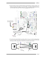
External Analogue Input.

A signal applied to this connector will

feed the right hand side of the A to D

converter in all ‘stereo’ modes.

External Sync Input.

Either AES/EBU or

TTL wordclock are

accepted.

ADC Lock

Indicator

Summary of Contents for XLogic Super-Analogue

Page 1: ...Solid State Logic Super Analogue Outboard Owner s Manual 82S6XL070A S U P E R A N A L O G U E C H A N N E L A D C...

Page 2: ...55 14 Sendagaya Shibuya Ku Tokyo 151 0051 Japan 81 0 3 5474 1144 7 bis rue de la Victoire le Blanc Mesnil Paris 93150 France 33 0 1 48 67 84 85 Via Timavo 34 20124 Milano Italy 39 0 39 2328 094 Visit...

Page 3: ...al Safety Warnings Installation 3 Installation 6 Supplied Parts Tools Required Procedure 4 Operation 11 Synchronisation Sample Rates Appendices 15 A Internal Links B Connector Details C Electronic Spe...

Page 4: ...lower of the 629605 Channel ADC card XLogic Channel ADC Owner s Manual Page 2 AES OUT SPDIF OUT SYNC IN RIGHT IN SAMPLE RATE SYNC Fs x 44 1 1 4 1 2 AES Fs INT Fs 48 4 SINGLE 2 4 SINGLE 4 WD CLK 256 x...

Page 5: ...r if you are unsure about performing this please contact your local Solid State Logic distributor who will be happy to arrange to install it for you Do note that a charge may be levied for this servic...

Page 6: ...rs and competent operators skilled in the use of professional audio equipment Environment This product is a Class A product intended to form an integrated component part of a professional audio record...

Page 7: ...t 15 of the FCC Rules These limits are designed to provide reasonable protection against harmful interference when the equipment is operated in a commercial environment This equipment generates uses a...

Page 8: ...ts The following hardware is supplied with the XLogic Channel ADC Card kit Qty Item Part Number Description Notes 10 51DD20CB Screw M3 x 6mm Csk Pozi Zp Spares for the top cover 6 51DD25CB Screw M3 x...

Page 9: ...ver as the tip of a pozi drive screwdriver is quite blunt and has additional flutes between each of the four blades that make up the head as shown in the illustration to the right a philips screwdrive...

Page 10: ...top cover to the unit Lift the cover off and place it safely to one side 2 Turn the unit around and using the same screwdriver remove the two M3 x 6mm panhead screws which fix the ADC blanking plate...

Page 11: ...1 cables on the main PCB to avoid them snagging under the ADC card 4 The ADC card is retained in the XLogic unit by a total of six screws two for the rear plate and four for the PCB Loosely fit four M...

Page 12: ...e correct position if in doubt leave it at the factory 24dBu setting 8 Refit the top cover to the XLogic unit and replace the 15 M3 x 6mm Csk screws we have supplied a few replacements if any were dam...

Page 13: ...to be set to match the nominal rate being applied Word Clock In this mode the ADC card will lock to an external TTL level word clock at any nominal sample rate between 44 1kHz and 192kHz again set sw...

Page 14: ...kHz This sets the ADC to run at 176 4kHz stereo For external sync at this rate the applied AES or Word Clock sync should be 176 4kHz Super Clock is not supported 192kHz This sets the ADC to run at 192...

Page 15: ...V pk pk or unbalanced 75 AES EBU 1V pk pk Conversion from balanced to un balanced AES EBU is best achieved with a third party in line transformer These are widely available your local Solid State Logi...

Page 16: ...XLogic Channel ADC Owner s Manual Page 14...

Page 17: ...nnector Details SPDIFOut Location Rear Panel Conn Type RCA Phono Pin Description Tip Signal Sleeve Chassis AES Out Location Rear Panel Conn Type XLR Male Pin Description 1 Chassis 2 Signal ve 3 Signal...

Page 18: ...cation are as follows Reference frequency 1kHz Reference level 0dB FS 24dBu Source impedance of Test Set 50 Unweighted measurements are specified as 22Hz to 22kHz band limited RMS and are expressed in...

Page 19: ...5 x 2 5 Boxed weight 350g 12 ounces All weights and dimensions are approximate Appendix E Environmental Specification Temperature Operating 5 to 30 Deg C Non operating 20 to 50 Deg C Max Gradient 15...

Page 20: ...XLogic Channel ADC Owner s Manual Page 18 Notes...

Reviews: