


XLogic Channel ADC Owner’s Manual
Page 6
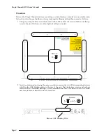
3.
Installation
This section details how to install the XLogic Channel ADC card in an XLogic Channel unit. Before you
begin, please consider these points:
• Carefully read through these instructions first.
• Check that all of the component parts of the kit are present.
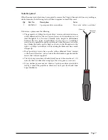
• Check that you have the required tools to hand before attempting installation.
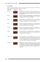
• Consider if you need to adjust the operating level of the card. There are two options, set by an
internal jumper:
+24dBu (position ‘1-2’)
0dBu ≈ –24dB FS (SMPTE standard and factory default)
+18dBu (position ‘2-3’)
0dBu ≈ –18dB FS (EBU standard)
Supplied Parts
The following hardware is supplied with the XLogic Channel ADC Card kit:
Qty
Item
Part Number & Description
Notes
10
51DD20CB - Screw M3 x 6mm Csk Pozi Zp
Spares, for the top cover…
6
51DD25CB - Screw M3 x 6mm Pan Pozi Zp
ADC Card fixings
4
51DDNH5Z - Washer M3 Fibre
Internal ADC Card fixings
2
51DDNQ5B - Washer M3 Crinkle Shakeproof Zp
External ADC Card fixings
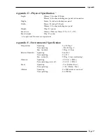
Also included in this kit are one of each of the following:
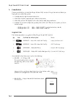
• 629605X1 - S/A XLogic ADC
This card should be left in its sealed,
anti-static bag, until you are ready to
install it.
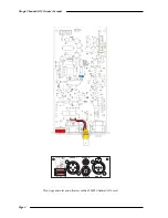
Along with the card there should also be a short ribbon cable
(either loose or plugged into PL5 on the ADC card).
• 82S6XL070A - XLogic Channel ADC Installation Guide
(this document)
Solid State Logic
Super-Analogue™ Outboard
Owner’s Manual
82S6XL070A
S U P E R A N A L O G U E
C H A N N E L A D C


