

Tools Required
Other than any tools which may be required to remove the XLogic Channel unit from any racking or
studio furniture, the following tool is all that is required to install this card:
Qty
Part No.
Description
Notes
1
80C2CECC
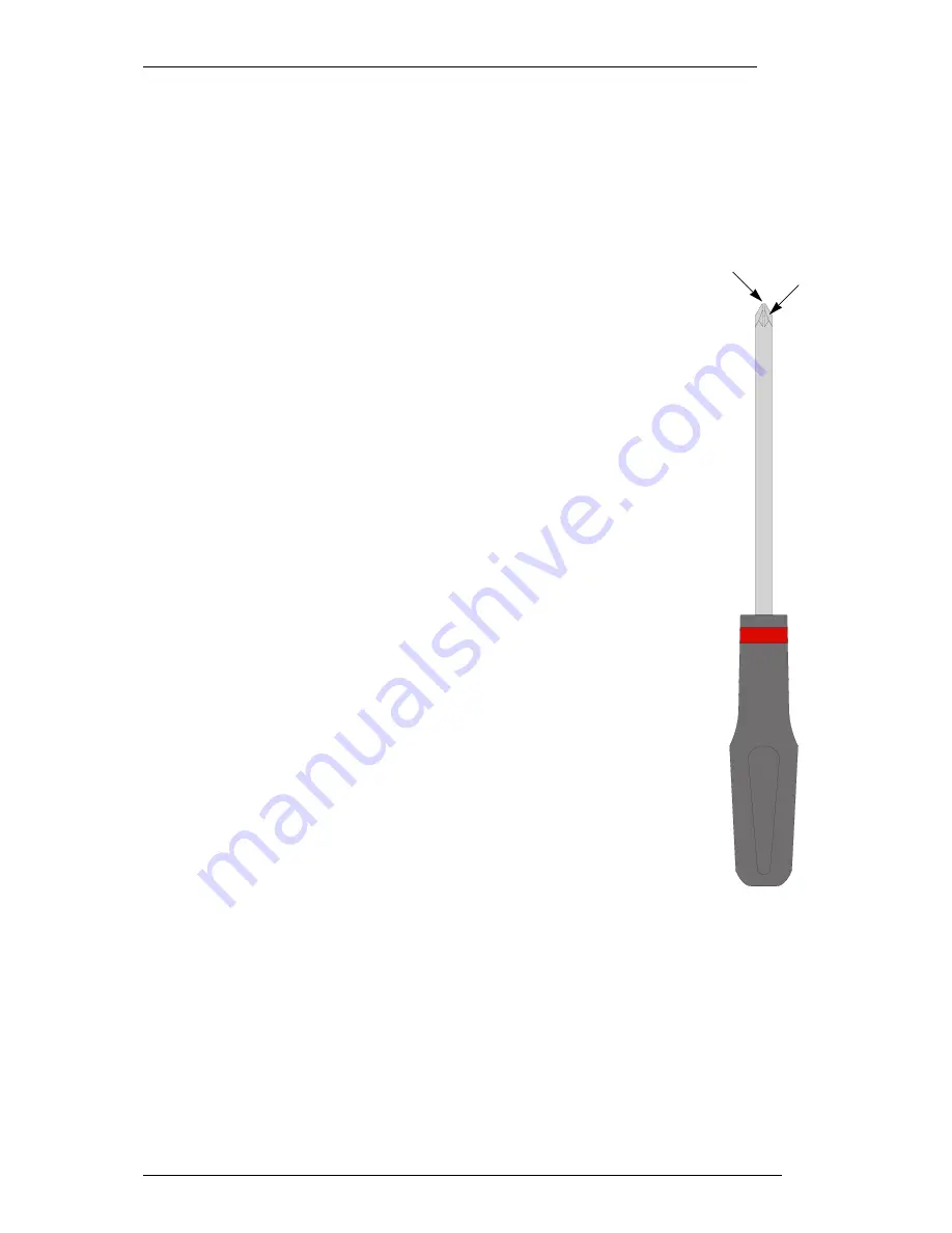
1-point pozi-drive screwdriver
This is not a ‘philips’ screwdriver!
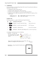
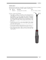
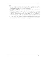
Do however, please note the following:
• The geometry of ‘philips’ and ‘pozi-drive’ screws and screwdrivers are
subtly different and so the two types of screw and screwdriver are not
inter-changable. It is however normally quite simple to differentiate
between the two types of screwdriver as the tip of a ‘pozi-drive’
screwdriver is quite blunt and has additional ‘flutes’ between each of the
four blades that make up the head, as shown in the illustration to the
right – a ‘philips’ screwdriver will be missing the flutes and has a much
sharper tip.
• Most ‘pozi-drive’ screws have an echo of the additional ‘flutes’ marked
on the head of the screw - take a look at the illustrations opposite and the
screws that we have supplied.
• The tip of any screwdriver should firmly locate in the screwhead – if it
does not then it is either the wrong type, the wrong size or worn out.
• If you neither possess nor can obtain a 1-point pozi-drive screwdriver
locally, it should be possible to obtain one from your local Solid State
Logic distributor.
Installation
Page 7
Additional
‘flutes’
Blunt tip


