Levelogger User Guide - Software Version 3.4.0 or Higher
Page 43
11 Installation and Maintenance of Leveloggers
11.1 Installation
Many options exist for installation of the Levelogger, but essentially these
installation methods can be classified into two broad categories: free suspended
or fixed installations.
1. In free suspended installations, the Levelogger is hung via suspension wire
or Direct Read Cable from the well cap, or some fixed tie-off location, at the
well head.
2. In fixed installations the Levelogger is fixed in place by a compression fitting,
a clamping mechanism or simple metal straps.
Prior to commencing the discussion of installation techniques several general
points related to Levelogger installation should be made. First, it is recommended
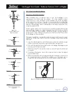
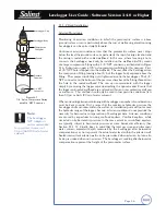
that the Levelogger be installed in a vertical orientation. However, inclined
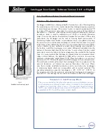
or horizontal installation is acceptable. The level sensor in the Levelogger is
indicated by the machined line about the body of the logger just above the
pressure access holes. The pressure transducer is oriented in a plane normal to
the long axis of the body and detects pressure directed along the plane of the
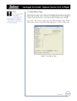
long axis (Fig 11.1). In vertical orientations, the sensor detects pressure above
the pressure transducer line, where as in non-vertical orientations, the pressure
zero point is proportional to the angle of inclination.
Care should be taken to avoid dropping the Levelogger against a hard surface.
Further, the pressure transducer can be damaged if the datalogger is over-
pressurized by submergence greater than its level range. The Levelogger is
warranted to pressures up to 150% of its full scale level range, however accuracy
can not be guaranteed beyond its full scale.
Other important considerations when installing the Levelogger in pressurized or
intermittently pressurized locations such as pressure vessels, pressurized pipes,
pulse flow conditions, drop structures or near hydraulics works, is to keep in
mind the potential effect of water or steam hammer and hydraulic jump. Water
hammer is caused by an abrupt alteration of flow direction resulting in pressure
surges. Steam hammer occurs when steam enters a cold pipe partially filled with
water. The hammer effect has the potential to significantly increase hydraulic
pressure possibly exposing the pressure sensor to pressures beyond its maximum
rating. Hydraulic jump is a phenomenon that occurs when water is ‘lifted’ or
‘ramped’ by velocity or flow obstructions. Hydraulic jump causes turbulence and
creates non-representative head conditions in the water column. Care should be
taken to avoid logger installation at points susceptible to hydraulic jump.
LTC Levelogger Junior
and Levelogger Junior
Measurement Line
Levelogger Gold
Measurement Line
Figure 11-1
Note:
When using Direct
Read Cables, the
following maximum
lengths apply to the cable
according to which PC
Interface Cable is to be used:
• USB PC Interface Cable:
1,000 ft (300 m)
• RS232 PC Interface Cable:
500 ft (150 m)
• RS232 PC Interface
Booster:
1650 ft (500 m)

