.15.
.14.
4. Installation
4. Installation
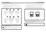
Terminal block
Housing
Cable gland
5. Make sure the rib of the terminal block and the groove on the housing engage perfectly
until a “click” is heard to felt.
4. Each of the terminals are labeled. Ensure that the correct conductor is fastened
(1.2 N.m. torque) to the correct terminal.
1. Make sure you use a cable within the correct specifications as shown in the image below.
3. Remove a length of 40mm of the cable jacket and strip the wire insulation to a length of
8 – 15mm.
2. Lead the AC cable through the cable gland and the housing.
Describe
Wire diameter
10~12mm
2.5~6mm
²
12mm
Traverse cross sectional area
Exposure Length
Numerical value
40 mm
8 mm - 15 mm
PE
L
N
There are two AC terminals and the assembly steps for both are the same.
Take
out
the
AC
connector
parts
from
the
packaging
.
4.5 Assembling
the
AC
Connector


