1
SLS-ENVR2016-xT_2.2.2_RQ
9/26/13
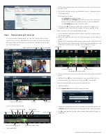
Front panel LEDs indicate the following:
•
Network activity LED
: Lights when the network cable is connected, blinks during network activity.
•
Tray 1, Tray 2 active LEDs
: Blink when the HDD is accessed.
•
Power, Information LEDs
: These LEDs function as a pair to indicate the status of the NVR. See the
table below.
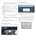
Power LED
Information LED Status
—
—
Power supply connect
—
—
Off
On
Off
Normal mode
Off
On
Rescue mode
Blinking
Off
Starting
On
Blinking
Found by the Discover utility
On
Fast blinking
Factory reset in progress
Retaining
screw
Tab latch
Retaining
screw
“1”
“2”
Control
button
Control
button LED
Network
connectors
USB
(not used)
Power
connector
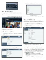
Back panel
Use the connectors, indicators and switch on the back of the NVR as follows:
•
Control button LED
: Indicates the usage state of the control button (see table below)
•
Control button
: Pressing the Control button can affect the DVR in three different ways, depending
on how long the button is pressed. Pressing the button for less than 5 seconds signals a “
short
” press,
pressing the button for 5 ~ 10 seconds signals a “
long
” press, pressing the button for more than 15
seconds signals a “
very long
” press. The NVR reacts differently to these presses depending on the
status. See the table below.
Power
LED
Informa-
tion LED
Status
Short press ( < 5 s)
(Control LED lights)
Long press
(5 - 10s) (Control
LED blinks)
Very long press
(> 15 s) (Control
LED blinks fast)
—
—
Power supply
connect
Start
Factory reset
—
—
—
Off
Start
Start
—
On
Off
Normal mode
Rescue mode
Shutdown
Hard shutdown
Off
On
Rescue mode
Normal mode
Shutdown
Hard shutdown
Blinking
Off
Starting
On
Blinking
Found by the
Discover utility
On
Fast
blinking
Factory reset in
progress
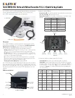
The SLS-ENVR2016 series NVR is an intelligent and compact appliance that provides a network interface
to monitor, record and playback video from up to 16 IP cameras. It is very easy to install and use.
Your SLS-ENVR2016 product includes components shown in the picture below.
Software CD
SLS-ENVR16 NVR
Ethernet
cable
Quick Setup
Guide
Power adapter
with cable
HDD extractor
What you need
Your SLS-ENVR2016 NVR hardware is pre-configured with HDD(s). If you want to change the HDD or
configure it differently (RAID options, trays, etc.), refer to the document
SLS-ENVR Series Network
Video Recorder V2.2.2 User Manual
provided on the Software CD for specific instructions.
A PC is required to access and control your NVR. It must meet the following requirements:
•
Operating system
: Microsoft® Windows® 2003, 2008, XP, Vista, 7 and 8 (32- and 64-bit versions);
Apple® OS X® 10.6, 10.7, 10.8; Linux with 2.6 kernel or newer (Oracle Java recommended)
•
Internet browser
: Mozilla® Firefox® 17 ESR, 20 or newer; Internet Explorer® 8 (with performance
limitations, 32-bit version), 9, 10 (32-bit version); Google Chrome® 26 or newer; Apple Safari® 5.1 (on
Mac OS X only). JavaScript and cookies must be enabled.
•
Java
™: Oracle® Java 6.0 or newer is required. The latest version of Oracle Java 7 is recommended.
•
MPEG4 and H.264 support for the viewer applet requires installation of native libraries to the client
computer. The libraries are automatically installed by the Java applet.
•
Client computer hardware configuration
: Computer with 1GB RAM
The SLS-ENVR2016 allows the user to download videos and pictures from videos saved on a hard disk. The
pictures are in standard JPEG format and can be displayed in every standard picture browser. To play video,
install an FFDShow CODEC (download from
http://www.freecodecs.com/download/FFDshow.htm
) or similar
filter. Also, VLC player contains the CODEC necessary to play SLS-ENVR videos (download at
http://www.
videolan.org
).
NVR buttons and indicators
Power LED
Light strip
Tray 1 HDD
active LED
Tray 2 HDD
active LED
Network
activity LED
Information
LED
SLS-ENVR2016 front panel
SLS-ENVR2016 Network Video Recorder V2.2.2 Quick Setup Guide


