background image

9

1.OPERATING TRANSMITTER:

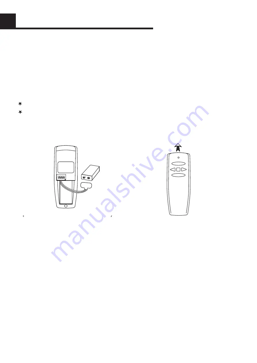
A. Install 9 volt battery(not included). (To prevent damage to transmitter, remove the battery if not used for a long time).


B. Store the transmitter away from excessive heat or humidity.

C. This remote control unit is equipped with 16 code combinations. In order to prevent possible interference from or to 

         other remote units such as garage door openers, car alarm or security system. If you find that your fan and light kit go 


on and off without using your remote control, simply change the code combination in your transmitter and receiver.


D. Operating the buttons on the panel of the transmitter.

HI key -for fan high speed.

MED key-for fan medium speed.

          LOW key-for fan low speed.

          OFF key-for fan off.


YOUR REMOTE NOW HAS FULL CONTROL OF THE FAN AND LIGHT.

FAN OFF

LO

HI

MED

LIGHT/DIMMER

OPERATION DISTANCE 20 FEET

TRANSMITTER

MODEL:

HK-01

 Optional Wall Mounting for Transmitter Holder

Place in accessible area of your home, and screw the 

transmitter holder into wall using the two screws 

provided, slide hand unit into holder.

2. TROUBLE SHOOTING GUIDE

NOTICE !

ON

1  2  3  4

BA

TT

ER

Y

9  

VOL

T

WARNING

a.Make sure power is correctly connected to the receiver.

b.Make sure the fan pull chain (if included) at highest position.

c.Make sure the light kit switch turned on.

d.Make sure good battery in ransmitter

.

e.Make sure the code set at exact same positions in both transmitter and receiver.

f.Make sure the transmitter operates with in 20 feet away from the ceiling fan.

The light function is controlled by pressing the LIGHT/DIMMER key down to increase or decrease light.

Tap key quickly to turn light off or on.

Keep pressing the button in excess of 0.7 second and it becomes a dimmer, the light varies cyclically in 0.8 second.

The receiver can remember the last status of the light brightness when the light was switched, so that it can

resume to adjust the light brightness.

LIGHT/DIMMER key-for light brightness and off.

Your ceiling fan and light kit assembly must meet the following requirements:

1. Do not use with solid state fans.

2. Electrical rating: 120v 60Hz 3.5A

MAX. Motor amps: 1.0

MAX. Light watts: 240-(incandescent or LED)

TO REDUCE THE RISK OF SHOCK, THIS FAN MUST BE INSTALLED WITH A WALL CONTROL/SWITCH.

NOTE: THE MANUFACTURER IS NOT RESPONSIBLE FOR ANY RADIO OR TV INTERFERENCE CAUSED

BY UNAUTHORIZED MODIFICATIONS TO THIS EQUIPMENT. SUCH MODIFICATIONS COULD VOID THE

USER'S AUTHORITY TO OPERATE THE EQUIPMENT.

REMOTE OPERATION

Summary of Contents for LTG-CF5001

Page 1: ...READ AND SAVE THESE INSTRUCTIONS CEILING FANS INSTALLATION INSTRUCTION MODEL SERIES LTG CF5001 ...

Page 2: ... electrical system and choice of location meet these requirements If the location where you plan to install your fan does not already have an electrical outlet hire a licensed electrician to run the wiring and install an outlet box designed for ceiling fans or heavy fixtures The outlet box should be able to support a mini mum moving weight of 50 pounds and marked Acceptable for Fan Support Plastic...

Page 3: ...isk of fire electrical shock or personal injury mount this fan to an outlet box marked Acceptable for Fan Support and use the Mounting Screws provided with the outlet box CAUTION Install the primary mounting means and use only the hardware provided with the fan To reduce the risk of personal injury take care not to bend the blade carriers Be careful not to insert foreign objects into rotating fan ...

Page 4: ... 2 from the bracket as shown above Install mounting bracket to outlet box in ceiling using the screws and washers provided with the outlet box MOUNTING BRACKET INSTALLATION 1 1 2 2 PREPARING FOR INSTALLATION Phillips Screwdriver Flat Blade Screwdriver Step Ladder Wire Stripper 1 2 TOOLS NEEDED 3 4 Unpack the carton and inspect the fan carefully to be sure all contents are included Please kindly ke...

Page 5: ...acket into slot opening of mounting plate This will allow for hands free wiring Press Board Mounting Plate MOUNTING INSTALLATION Please refer to page 8 9 for remote controller and receiver installation and operation detail 1 2 3 Place the remote control receiver on the plate and connect wire and then pull all wires STRAIGHT and TIE them well with provided plastic cable in screw pack to prevent mot...

Page 6: ...ectly under and in line with two screws in the mounting bracket 3 Lift the motor housing allowing the two screws to slide into the mating slots Rotate the motor housing clockwise until both screws from the mounting bracket drop into the slot recesses Tighten screws securely Install two screws and star washers into the mating holes of the motor housing and tighten to secure the housing to the mount...

Page 7: ...ll prior to changing directions Reverse switch on fan should ideally be set on FORWARD DOWN position during hot seasons to move blades in an anticlockwise direc tion REVERSE UP position in cold seasons to make the fan rotate in clockwise direction Attach blade brackets to blades using the blade bracket screws 1 metal washers 2 and fabric washers 3 if provided NOTE Some models do not utilize fabric...

Page 8: ...white wire from the switch housing to the white wire from the light kit Attach light kit to the switch housing using three small screws provided 7 Install shades to light kit by finger tightening the screws for each shade holder as shown Do not over tighten screws Install light bulbs in cluded LIGHT FIXTURE INSTALLATION 1 2 Tip Dimmable LED bulbs can use the dimmer function ...

Page 9: ... of up or down position Factory setting is all up Do not use this position Use a small screwdriver or ball point pen to slide firmly up or down Figure 1 Setting the codes on the receiver B a Slide code switches to the same position as set on your transmitter Figure 2 b Replace battery cover on the transmitter 2 INSTALLING RECEIVER IN CEILING FAN Safety precautions A WARNING HIGH VOLTAGE Disconnect...

Page 10: ... sure power is correctly connected to the receiver b Make sure the fan pull chain if included at highest position c Make sure the light kit switch turned on d Make sure good battery in ransmitter e Make sure the code set at exact same positions in both transmitter and receiver f Make sure the transmitter operates with in 20 feet away from the ceiling fan The light function is controlled by pressin...

Page 11: ...10 PARTS INVENTORY Led Bulb x3 x5 x5 x3 x3 ...

Page 12: ... kit make sure the screws securing the glassware are tight Make sure the light bulbs are not touchingany other component 2 Fan sounds noisy Check that all blade and blade arm screws are secure Most fan wobbling problems are caused by blade levels unequal Check this level by selecting a point on the ceiling above the tip of one of the blades Measure this distance Rotate the fan until the next blade...

Reviews: