background image


10K Pack HV Installation Manual 

© 2021 Soluna Australia Pty Ltd 

Page 18 of 25 

Published date: March 2021 


Electrical connection 


Please refer to the following diagram for details of double pole isolation of 10K Pack HV 

battery systems. 


BAT +  

BAT -

DC

 In

pu

t

CAN 1

CAN 1

Inverter

POS +

NEG -

10mm

10mm

10mm

10mm

So

lu

na

 1

0K

 p

ac

k

DP 40a 

500VDC


Preparation 


Summary of Contents for 10K Pack HV

Page 1: ...ual 2021 Soluna Australia Pty Ltd Page 1 of 25 Published date March 2021 Installation Manual Lithium Battery Pack SOLUNA 10K Pack HV Suitable for indoor installation Soluna Australia Pty Ltd ACN 634 963 296 March 2021 Version 2 2 ...

Page 2: ...Perth WA 6005 The information included in this manual is accurate at the time of publication However with respect to product design and technical specification updates Soluna Australia reserves the right to make changes at any time without prior notice Further the illustrations in this manual which help explain system configuration concepts and installation instructions may differ from the actual ...

Page 3: ...gencies 6 Leaking batteries 6 Fire 6 Wet batteries 6 Damaged batteries 6 Accredited installers 6 Safety equipment 7 2 Product introduction 8 Features 8 Application 8 Unpacking the BS 8 Packing list 9 Installation materials 9 Installation location 9 Installation tools 10 Outline dimensions mm 11 Technical data 12 Appearance 13 Wiring port 14 3 Installation 15 Space requirements during installation ...

Page 4: ...re that battery polarity is observed and that the BS is connected correctly Keep the BS away from an open flame or sources of ignition Keep children and animals away from the BS Read the manual in its entirety before installing and operating the BS The BS is heavy enough to cause severe injury if not handled correctly The BS contains electrolyte which is corrosive if it leaks The BS may explode if...

Page 5: ...the BS connectors to touch conductive objects such as wires Risks of electric shock 1 Do not disassemble the BS as high DC voltage may be present 2 Do not touch the BS with wet hands 3 Do not expose the BS to moisture or liquids 4 Keep children and animals away from the BS Risks of damage to the BS 1 Do not allow the BS to come into contact with liquids 2 Do not subject the BS to high pressures 3 ...

Page 6: ...estion of the leaked substance 8 If ingestion does occur induce vomiting and seek medical attention immediately Fire Always keep an ABC or carbon dioxide fire extinguisher nearby in case of fire The BS may catch fire if heated above 150 Celsius If there is a fire near or at the location in which the BS is installed do the following 1 If it is safe to do so extinguish the fire before the BS ignites...

Page 7: ...that is a trained and qualified electrician with the following skills and experience 1 Knowledge of the functional principles and operation of on grid systems 2 Knowledge of the dangers and risks associated with installing and using electrical devices as well as acceptable mitigation methods 3 Knowledge of the installation of electrical devices 4 Knowledge of and adherence to this manual aswellasa...

Page 8: ... and under temperature protection functions It is characterised by high energy density long life safety and reliability and is environmentally sustainable Features 1 Excellent safety performance 2 Long cycle life 3 Support for CAN communication 4 High energy density 5 Excellent BMS Application 1 Back up power 2 Micro grid 3 Home energy storage system Unpacking the BS Remove the nails from the wood...

Page 9: ...9 CAN communication wire 1 Installation materials Installers should prepare the following installation materials 1 Battery connection charging cables 2 Network connection cables Installation location Ensure that the installation location meets the following requirements 1 The building is designed to withstand earthquakes 2 The BS location is internal and out of direct sunlight 3 The floor is flat ...

Page 10: ... tools are required to install the BS Item Photo Name 1 Phillips screwdriver bit 2 Network crimper 3 Wire cutter 4 Wire stripper 5 Tape measure All tools should be appropriately insulated to prevent accidental electric shock or short circuits Use adjustable tools and measuring instruments that are certified for precision and accuracy ...

Page 11: ...Installation Manual 2021 Soluna Australia Pty Ltd Page 11 of 25 Published date March 2021 Outline dimensions mm Figure 2 1 outline dimensions Depth Width Width mm 647 2 Depth mm 227 2 Height mm 905 3 Weight kg 103 ...

Page 12: ...ent A 30 30 Charge discharge power nominal kW 4 2 Max charge discharge power kW 8 DoD 80 Cycle life 3600 Battery pack round trip efficiency 95 DC disconnect Contactor fuse BMS Power consumption mA 100 work 0 1 sleep Monitoring parameters System voltage system current cell voltage cell temp Communication CAN Operating conditions Operating temperature C 10 to 45 Operating temperature recommended C 1...

Page 13: ...llation Manual 2021 Soluna Australia Pty Ltd Page 13 of 25 Published date March 2021 Appearance Figure 2 2 appearance Number Name Remark Cable entry Power ON OFF Upper handle Lower handle Grounding Grounding Power light ...

Page 14: ...date March 2021 Wiring port The Soluna 10K PACK HV s wiring port is visible once the cover cap has been opened see diagram below for details Figure 2 3 Wiring port Number Name Remark CAN 1 port For external communication inverter CAN 2 port For internal communication BMS Battery Battery ...

Page 15: ... space of 200 cm in all directions around the BS Position Minimum spacing cm Remark Side spacing 100 Allow a clearance of at least 100 cm on either side of the BS Above 40 Nothing should be placed on top of the BS allow clearance of at least 40 cm Below Always use the floor mounting brackets supplied Their height is adjustable allowing the installer to ensure that the BS is level when installed mi...

Page 16: ...tails Wiring specification To standardise the BS wiring specification the following are required to connect the wires Battery wire Communication cable Use of a 10mm conductor with double insulation is recommended Use of communication cable with a shielding function is recommended Earth connection specification Step 1 drill holes in the wall Step 3 install the battery module Step 2 screw the bracke...

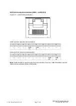
Page 17: ...interface CAN 1 and CAN 2 Figure 3 1 CAN interface definition CAN 1 port for external communication 1 2 3 4 5 6 7 8 CAN 1H CAN 1L CAN 2 port for internal communication 1 2 3 4 5 6 7 8 CAN 2H CAN 2L Note CAN 1H CAN 1L used for external communication inverter CAN 2H CAN 2L used for internal communication battery CAN ports ...

Page 18: ...8 of 25 Published date March 2021 Electrical connection Please refer to the following diagram for details of double pole isolation of 10K Pack HV battery systems BAT BAT DC Input CAN 1 CAN 1 Inverter POS NEG 10mm 10mm 10mm 10mm Soluna 10K pack DP 40a 500VDC Preparation ...

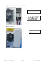
Page 19: ...s Step 1 Connect the earth cable Step 2 Create power cables Crimp the correct size cable lugs to the DC cables 10mm cable x 5mm centre hole The earth terminal and cable should be fastened with an M6 screw Crimp the cable lugs 10mm x 5mm with a wire crimping tool Heat shrink sleeve should be applied to the exposed conductive crimp lug ...

Page 20: ...ck power cables and communication cable Step 4 Lock the cover Remove communication cable from accessory box and plug CAN 1 into the inverter Lock power cable with a Phillips screwdriver M5 ensuring the correct polarity and a firm connection of 3NM torque Lock the terminal cover plate with a hexagon wrench 2 5mm ...

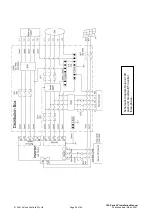
Page 21: ...10K Pack HV Installation Manual 2021 Soluna Australia Pty Ltd Page 21 of 25 Published date March 2021 Schematic diagram Soluna 10K pack and Goodwe EH Inverter single phase ...

Page 22: ...10K Pack HV Installation Manual 2021 Soluna Australia Pty Ltd Page 22 of 25 Published date March 2021 Schematic diagram Soluna 10K pack and Goodwe ET inverter three phase ...

Page 23: ... with cables 3 Turn on the circuit breaker found on the right side of the BS 4 To shut the battery down switch the circuit breaker from the On position to the circuit breaker Off position 4 Consumer Start up and Shut down procedure 1 To turn the BS on push the circuit breaker up the circuit breaker is located on the right side of the BS see diagram above 2 To turn the BS off push the circuit break...

Page 24: ...10K Pack HV Installation Manual 2021 Soluna Australia Pty Ltd Page 24 of 25 Published date March 2021 ...

Page 25: ...nit will be replaced if a failure is diagnosed It may be necessary to conduct product firmware upgrades during the life of the battery These will be conducted as required and carried out remotely by Soluna Australia on a need to do basis only 6 Contact us If you have any questions please feel free to contact Soluna Australia Phone within Australia 1300 126 888 within New Zealand 09 886 9685 Email ...

Reviews: