I/O Address Map
http://www.motorola.com/computer/literature
3-5
3
I/O Address Map
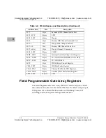
shows I/O addressing. You can use BIOS Setup or special
utilities to enable or relocate these features from their default values.
Table 3-2. I/O Addresses and Descriptions
Address (hex)
Size
Description
0000 - 000F
16 bytes
PIIX4E DMA, channels 0 - 3
0020 - 0021
2 bytes
PIIX4E Interrupt Controller 1
0040 - 0043
4 bytes
PIIX4E - Timer 1
005B
2 bytes
FPGA Watchdog Strobe/Status Register
005D
2 bytes
FPGA Index Register
005F
2 bytes
FPGA Data Register
0060
1 byte
Keyboard Controller
0061
1 byte
PIIX4E - NMI, Speaker Control
0064
1 byte
Keyboard Controller
0070 - 7
1 bit
PIIX4E NMI Enable
0070-6:0
7 bits
PIIX4E RTC
0071
1 byte
PIIX4E RTC
0072-0073
2 bytes
PIIX4E RTC (extended registers)
0080 - 008F
16 bytes
PIIX4E DMA Page Register
0092
1 byte
PIIX4E Port 92 Register
00A0 - 00A1
2 bytes
PIIX4E Interrupt Controller 2
00B2 - 00B3
2 bytes
APM reserved
00C0 - 00DE
31 bytes
PIIX4E DMA, channels 4 - 7
00EA
1 byte
Ultra I/O General Purpose I/O Index Register
00EB
1 byte
Ultra I/O General Purpose I/O Data Register
00F0
1 byte
Reset Numeric Error
0170 - 0177
8 bytes
Secondary IDE Channel
01F0 - 01F7
8 bytes
Primary IDE Channel
02F8 - 02FF
8 bytes
COM2
0376
1 byte
Secondary IDE Channel Command Port
Solution Systems Technologies Inc.
720-565-5995 | info@solusys.com | www.solusys.com
Solution Systems Technologies Inc.
720-565-5995 | info@solusys.com | www.solusys.com

