4-10
Computer Group Literature Center Web Site
Connector Pin Assignments
4
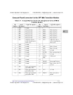
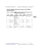
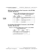
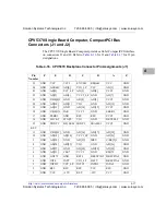
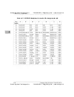
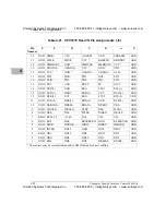
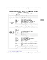
EIDE Connector for the CPTM04 Transition Module
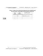
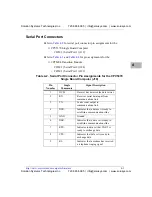
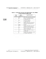
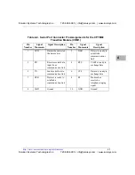
Table 4-10. EIDE Connector Pin Assignments for the CPTM04 Transition Module
Pin
Number
Signal
Mnemonic
Signal Description
Pin
Number
Signal
Mnemonic
Signal Description
1
RESET-
Reset signal to drive
2
GND
Ground
3
DD7
Drive data line
4
DD8
Drive data line
5
DD6
Drive data line
6
DD9
Drive data line
7
DD5
Drive data line
8
DD10
Drive data line
9
DD4
Drive data line
10
DD11
Drive data line
11
DD3
Drive data line
12
DD12
Drive data line
13
DD2
Drive data line
14
DD13
Drive data line
15
DD1
Drive data line
16
DD14
Drive data line
17
DD0
Drive data line
18
DD15
Drive data line
19
GND
Drive data line
20
-
-
21
DMARQ
Drive DMA request
22
GND
Ground
23
IOW-
Drive I/O write
24
GND
Ground
25
IOR-
Drive I/O read
26
GND
Ground
27
IORDY
Drive is ready for I/O
cycle(s)
28
CSEL-
Cable select
29
DMACK-
Drive DMA acknowledge
30
GND
Ground
31
INTRQ
Drive interrupt request
32
IOCS16-
Indicates a 16 bit
register is decoded
33
DA1
Drive register and data
port address line
34
PDIAG-
Output from drive 1
and monitored by
drive 0
35
DA0
Drive register and data
port address line
36
DA2
Drive register and data
port address line
37
CS1-
Chip select drive 0, also
command register block
select
38
CS3-
Chip select drive 1,
also command register
block select
39
DASP-
Drive active/slave present
40
GND
Ground
Solution Systems Technologies Inc.
720-565-5995 | info@solusys.com | www.solusys.com
Solution Systems Technologies Inc.
720-565-5995 | info@solusys.com | www.solusys.com

