http://www.motorola.com/computer/literature
4-11
4
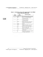
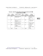
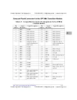
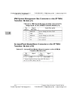
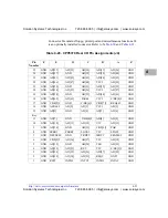
CompactFlash Connector for the CPTM04 Transition Module
Table 4-11. CompactFlash Connector Pin Assignments for the CPTM04
Transition Module
Pin
Number
Signal
Mnemonic
Signal Description
Pin
Number
Signal
Mnemonic
Signal Description
1
GND
Ground
26
-
-
2
DD3
Drive data line
27
DD11
Drive data line
3
DD4
Drive data line
28
DD12
Drive data line
4
DD5
Drive data line
29
DD13
Drive data line
5
DD6
Drive data line
30
DD14
Drive data line
6
DD7
Drive data line
31
DD15
Drive data line
7
CS1-
Chip select drive 0,
also command register
block select
32
CS3-
Chip select drive 1,
also command register
block select
8
GND
Ground
33
-
-
9
GND
Ground
34
IOR-
Drive I/O read
10
GND
Ground
35
IOW-
Drive I/O write
11
GND
Ground
36
VCC
+5 Volts
12
GND
Ground
37
INTRQ
Drive interrupt request
13
VCC
+5 Volts
38
VCC
+5 Volts
14
GND
Ground
39
CSE:L-
DD3
Cable select
15
GND
Ground
40
-
-
16
GND
Ground
41
RESET-
Reset signal to drive
17
GND
Ground
42
IORDY
Drive is ready for I/O
cycle(s)
18
DA2
Drive register and data
port address lines
43
-
-
19
DA1
Drive register and data
port address lines
44
VCC
+5 Volts
20
DA0
Drive register and data
port address lines
45
DASP-
Drive active/slave
present
Solution Systems Technologies Inc.
720-565-5995 | info@solusys.com | www.solusys.com
Solution Systems Technologies Inc.
720-565-5995 | info@solusys.com | www.solusys.com


