
GRW
Installation
10
GRW - Manual
|
SolutionAirGroup.com
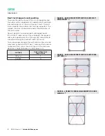
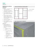
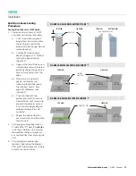
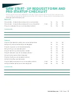
FIGURE 9: SECTION PLACEMENT
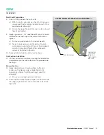
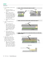
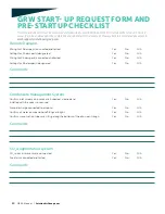
FIGURE 10: POSITIONED SECTION FASTENING BOLTS
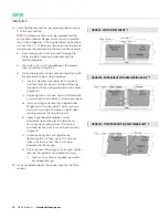
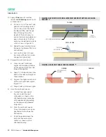
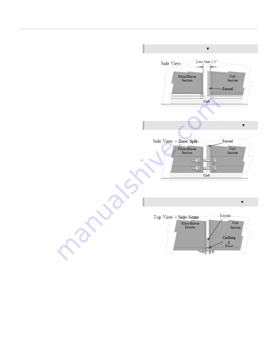
FIGURE 11: TIGHTENED SECTION FASTENING BOLTS
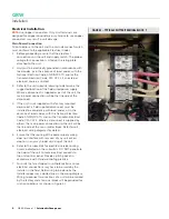
14. Install the blower-section, by lowering it down within
1” of the coil-section.
NOTE:
the blower-section must be lowered into the
coil-section receiver flange, which will aid in guiding
the sections together. If the gap between the sections
is more than 1.0”, the blower section cannot be pulled
into place without damaging the coil-section receiver.
a) A centering-punch shall be used (through the
lifting-lug bolt-holes) to guide and align the
sections together.
b) Ensure less than a 1.0” gap between the blower
and coil sections (Figure 9).
c) Fasten the blower and coil sections together (with
the provided stainless steel hardware).
i)
Insert 2” stainless steel bolts (with washers)
into the holes on the coil-section lifting lug,
through to the matching blower section holes
(Figure 10).
ii) Finger-tighten a stainless steel nut (backed by
a washer) onto the 4 bolts, as illustrated above.
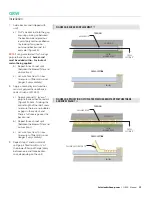
iii) Install and finger-tighten the supplied side-
flange bolts (stainless steel 1” bolts, washers,
and nuts), starting at the base on both sides,
moving towards the top of the unit.
iv) Apply a light bead of outdoor-rated
polyurethane caulking to the side-seams,
ensuring the caulking covers the Emseal
and touches the aluminum on both sections
(Figure 11).
v) Gradually bring the units together by
tightening the 4 lifting-lug nuts (2 on each
side), until there is less than a 1/8” gap
between the lifting lugs.
vi) Once the four lifting-lug nuts are tight, tighten
the side-flange bolts from bottom to top.
I) Clean off any sealant squeeze-out with a
dry disposable rag.
15. Once complete, repeat the above steps for the filter-
section.


