background image

GRW

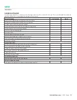
Installation

4

GRW - Manual 

  |   

SolutionAirGroup.com

Roof Curb Supports and Levelling

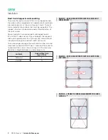
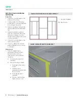
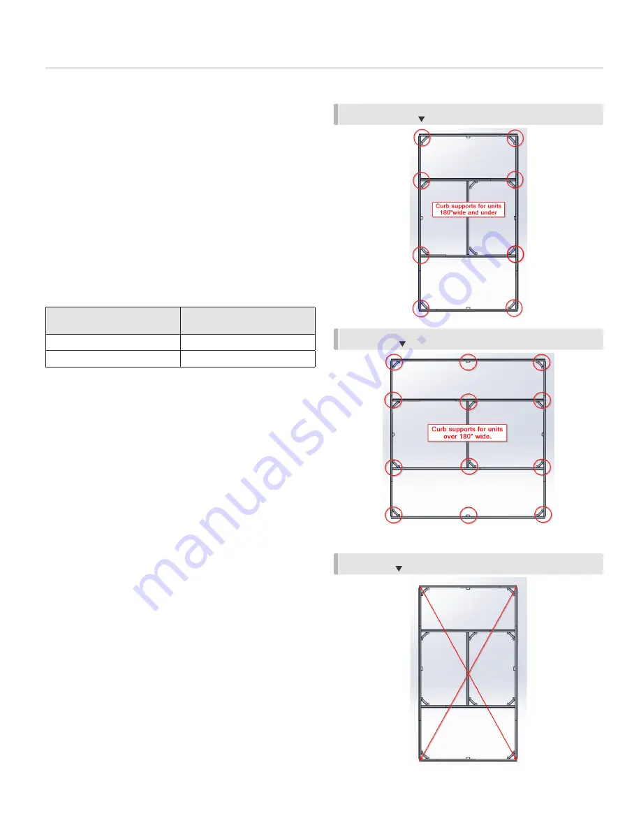
To ensure the roof curb and GRW unit is properly braced, 
the curb must be supported at all indicated roof curb beam 
intersection points, as shown in Figures 2 and 3. The red 
circles indicate intersections that must be supported.  The 
support structure is to be determined at the discretion of 
the unit’s owner. 

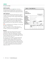
Figure 2 depicts the required roof curb support points 
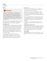
for units 180” wide and less. Figure 3 depicts the required 
roof curb support points for units over 180” wide. Refer to 
submittal drawings for the exact width of the unit. 

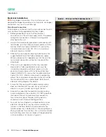
To ensure proper drainage, the roof curb must be installed 
more level or equal to 1/100” per 1’, measured from corner 
to corner of the curb as shown in Figure 4. The maximum 
deviation in height between any two corners is ¼”. 

Unit Width

Number of Roof Curb 

Support Points

180” or less

8

Over 180”

12

FIGURE 2 – ROOF CURB SUPPORT POINTS FOR UNITS 180” 

WIDE AND LESS  

FIGURE 3 – ROOF CURB SUPPORT POINTS FOR UNITS OVER 

180” WIDE  

FIGURE 4 –CORNER TO CORNER MEASUREMENTS FOR CURB 

LEVELING  

Summary of Contents for GRW

Page 1: ...MANUAL INSTALLATION GRW Precision Environmental Control Unit v003 Issue Date 03 03 20 2020 SolutionAir Group All rights reserved TM ...

Page 2: ...nstallation and Sealing 8 Split Roof Seam Sealing Procedure 11 Installation Checklist 15 Maintenance Filters 16 Fan and Motor Assembly 16 Service and Warranty Procedure 16 Maintenance Checklist 17 Troubleshooting 18 Start up Instructions 19 Typical Unit Sequence of Operation 20 GRW Start Up Request Form Pre Start Up Checklist 21 Limited Warranty 26 WARNING Fire or Explosion Hazard Failure to follo...

Page 3: ...tion may lead to electric shock possible injury from contact with moving parts and or possible burns from contact with heating components Additional safety concerns can arise from unit location such as a roof or inclement weather outdoor installations Additional safety precautions may be required Installer shall follow this manual and project submittals If these instruction conflict with any appli...

Page 4: ... photograph of any possible damage for record purposes Check the unit model number to make sure that it is correct If there are any issues do not proceed with the installation Contact your sales representative Storage If the unit is to be stored take precautions to prevent condensate from forming inside the unit s electrical compartments Make sure the equipment is protected from weather and dust f...

Page 5: ...vel If there is an external condensate drain check that there is enough height for the required condensate traps and that a means of removing the condensate is located nearby Generally the curb is shipped in advance of the unit delivery It should be installed along with any required ductwork prior to unit installation Where a roof curb has been supplied in knocked down condition absolute care must...

Page 6: ...points for units 180 wide and less Figure 3 depicts the required roof curb support points for units over 180 wide Refer to submittal drawings for the exact width of the unit To ensure proper drainage the roof curb must be installed more level or equal to 1 100 per 1 measured from corner to corner of the curb as shown in Figure 4 The maximum deviation in height between any two corners is Unit Width...

Page 7: ...nit inlet or discharge section is provided as part of the unit for example an access door in the unit access panels are strongly recommended for inspection and service Blower or Fan GRW units include direct plenum fans The motor fan frame and mounts should be visually inspected before initial start up and at every fan service The blower fan and motor are aligned before shipping from the factory sh...

Page 8: ...ect 4 If the unit is not supplied with a factory mounted disconnect a field supplied disconnect must be installed in accordance with local codes or in the absence of local codes with the National Electrical Code ANSI NFPA 70 and or the Canadian Electrical Code CSA C22 1 Where a disconnect is supplied by others the main power connection to the unit will be the line side of the main splitter block R...

Page 9: ...fts or in the warm supply air stream of the unit 3 On indoor units do not mount the thermostat or sensor on the unit casing as it may be affected by heat radiating off the unit 4 Do not place near other sources of warmth such as lamps appliances etc 5 Refer to unit electrical wiring diagrams for details on how to wire the sensor to the control panel 6 Ensure that all remote wiring is equivalent to...

Page 10: ... will require these to prepare the curb unit for installation 5 Check for visual damage on the interior of all sections 6 Clean any debris accumulated during shipping from air tunnels as required Materials List 7 Remove shipped loose components from the filter blower sections that are necessary for unit installation including a Curb acoustic sealant if included b Unit split sealing materials i Foa...

Page 11: ...igure 6 a Ensure no gaps breaks in the sealant bead s b Sealant is only necessary on the parts of the curb which come in contact with the unit Duct supports and cross members if present do not require sealant as illustrated in Figure 6 10 Proceed with installation of the unit sections Coil Section Installation 11 Lift the coil section into place ensuring that orientation and placement on the roof ...

Page 12: ...s steel hardware i Insert 2 stainless steel bolts with washers into the holes on the coil section lifting lug through to the matching blower section holes Figure 10 ii Finger tighten a stainless steel nut backed by a washer onto the 4 bolts as illustrated above iii Install and finger tighten the supplied side flange bolts stainless steel 1 bolts washers and nuts starting at the base on both sides ...

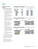
Page 13: ... the placement carefully remove clear backing Let Emseal strip expand into place may take 5 60 minutes depending on outdoor temperature and humidity f Repeat the above steps for each roof seam end four total for each unit 2 Firmly apply sealing tape such as 3 wide 3M 8777 over the interior roof seams between the coil and blower filter sections to prevent any sealant drips from entering the unit 3 ...

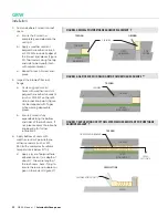
Page 14: ...m and sides of the roof seam If not please contact SolutionAir engineering for further instructions 6 Apply bottom of seam with weather resistant polyurethane adhesive sealant such as 3M 550 with accelerator if ambient temperature is below 10 C a Apply a layer of polyurethane adhesive sealant to a depth of about the entire length of the roof seam back filling to ensure there are no bubbles or gaps...

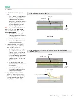
Page 15: ...e adhesive sealant such as 3M 550 a Apply a second layer of polyurethane adhesive sealant Figure 19 Back fill along the entire length of the roof seam to ensure there are no bubbles or gaps in the sealant and there is full coverage over the backer rod b Repeat for each roof split between the blower filter and coil sections c Let cure for at least 1 hour to ensure sufficient skin over longer if ver...

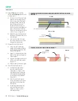
Page 16: ...to which the VHB tape will be applied b Apply 1 VHB tape to the entire back of the roof split angles as shown below c Dog ear the tape on each end of the roof split cover angles Figure 21 d Prep all roof split cover angles 12 Install the roof split covers a Starting from one side of the unit install the roof split covers as shown in the attached drawing removing VHB tape backing by pulling on the ...

Page 17: ...t for electrical supply if required Set unit on curb or housekeeping pad Ensure unit is level Seal bolt and cap all split joints as required Remove shipping hold downs shipping braces etc from unit Check all fan isolators for proper adjustment and operation Install filters as required Electrical Connections Confirm that main electrical supply matches the name plate requirements Inspect control cab...

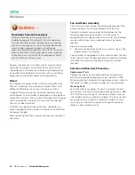
Page 18: ...fans therefore it is recommended that the unit be shut down while the filters are being changed When replacing the filters inspect the louvers and clean if necessary Fan and Motor Assembly The fan motor access panel should only be opened if the power has been shut off and locked off for the unit Review the blower service label on the blower for the recommended service frequency The controller if e...

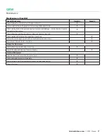
Page 19: ... all dampers and damper actuators adjust and tighten as required X Check cooling coils for cleanliness and clean as necessary X Inspect for worn compressor contactors annually and replace every 5 years X Remove and lubricate stainless steel bolts X Blower Fan Maintenance Check all bearings and lubricate as necessary X Inspect fan wheel and housing Clean as necessary X Electrical Maintenance Check ...

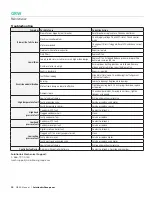
Page 20: ...te bearings Replace worn bearings Motor frame dampers loose ineffective Tighten mounting bolts Check springs dampers replace as required Dampers loose Check damper blades if moving in airstream tighten linkages as required High temperature fault Low refrigerant charge Will require mechanical service Faulty expansion valve Service or replace valve motor Faulty temperature sensor Service or replace ...

Page 21: ...the unit it is crucial to check the incoming electrical power 1 Check that the electrical power matches what is stated on the nameplate 2 Check that the voltage on each leg is within the stated voltage range and or does not deviate in excess of 10 of name plate value 3 Check that the voltage difference between all three phases is within 2 If any of these conditions are not met do not continue comm...

Page 22: ...city and airflow to bring the space to the user set points for the light cycle 6 Steady state operation Unit establishes operating conditions based on light sensor Unit modulates refrigeration capacity reheat capacity airflow and air paths to match the dehumidification and cooling requirements of the space for the detected light condition 7 Transition between Lights On to Lights Off BMS notificati...

Page 23: ...ART UP REQUEST FORM AND PRE STARTUP CHECKLIST This form and checklist must be completed and submitted to SolutionAir before the first startup of the listed unit Limited warranty will be enabled upon the completion and submittal of this document Please submit this completed document to mechsupport solutionairgroup com General Unit Information Start up Request Contractor Information Job Name Request...

Page 24: ...s etc useful Yes No N A How could we make them better Additional comments and suggestion on how to improve our products and services 22 GRW Manual SolutionAirGroup com GRW START UP REQUEST FORM AND PRE STARTUP CHECKLIST This form and checklist must be completed and submitted to SolutionAir before the first startup of the listed unit Limited warranty will be enabled upon the completion and submitta...

Page 25: ...START UP REQUEST FORM AND PRE STARTUP CHECKLIST This form and checklist must be completed and submitted to SolutionAir before the first startup of the listed unit Limited warranty will be enabled upon the completion and submittal of this document Please submit this completed document to mechsupport solutionairgroup com Network Ethernet cable Connected from building switch to main controller Yes No...

Page 26: ...ld we make them better Additional comments and suggestion on how to improve our products and services 24 GRW Manual SolutionAirGroup com GRW START UP REQUEST FORM AND PRE STARTUP CHECKLIST This form and checklist must be completed and submitted to SolutionAir before the first startup of the listed unit Limited warranty will be enabled upon the completion and submittal of this document Please submi...

Page 27: ...s Yes No N A Please describe the issue Were there any refrigeration system issues Yes No N A Please describe the issue Were the schematics manuals labels etc useful Yes No N A How could we make them better Additional comments and suggestion on how to improve our products and services 25 SolutionAirGroup com GRW Manual GRW START UP REQUEST FORM AND PRE STARTUP CHECKLIST This form and checklist must...

Page 28: ...er to prevent damage All freight back to SolutionAir s factory and return freight to Purchaser must be agreed upon prior to return of the Products 4 SolutionAir makes no warranty whatsoever with respect to components or items supplied which may be warranted separately by their manufacturer SolutionAir does not warrant factory mounted controls and components of Products supplied and owned by a thir...

Page 29: ...GRW Notes 27 SolutionAirGroup com GRW Manual ...

Page 30: ...This document contains the most current product information as of this printing For the most up to date product information please go to SolutionAirGroup com 2020 SolutionAir Group All rights reserved ...

Reviews: