

GRW
Installation
6
GRW - Manual
|
SolutionAirGroup.com
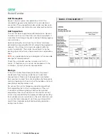
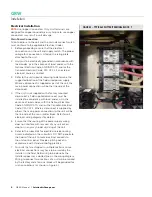
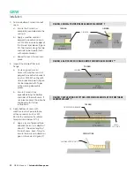
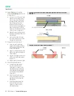
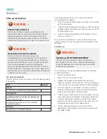
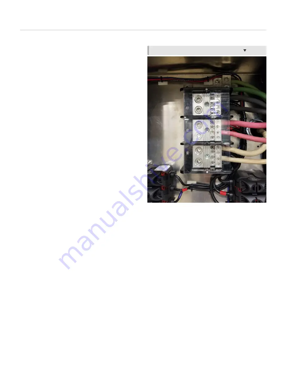
FIGURE 5 – TYPICAL SPLITTER/TERMINAL BLOCK
Electrical Installation
NOTE:
Use Copper Conductors Only: Unit terminals are
designed for copper conductors only. Failure to use copper
conductors may result in unit damage.
Main Power Connection
All connections to the unit and the main disconnect switch
must conform to the applicable Electrical Codes
1. Before proceeding, ensure that the electrical
connections on the unit and supply match. The proper
voltage for connection is listed on the rating plate
attached to the unit.
2. Unit must be electrically grounded in accordance with
local codes, or in the absence of local codes, with the
National Electrical Code, ANSI/NFPA 70, and/or the
Canadian Electrical Code, CSA C22.1, if an external
electrical source is utilized.
3. Refer to the unit submittal drawing to determine the
suggested location of the field wired power supply.
Where a disconnect is supplied as part of the unit, the
main power connection will be the line side of the
disconnect.
4. If the unit is not supplied with a factory mounted
disconnect, a field supplied disconnect must be
installed in accordance with local codes, or in the
absence of local codes, with the National Electrical
Code, ANSI/NFPA 70, and /or the Canadian Electrical
Code, CSA C22.1. Where a disconnect is supplied by
others, the main power connection to the unit will be
the line side of the main splitter block. Refer to unit
electrical wiring diagrams for details.
5. Ensure that the routing of the power supply wiring
does not interfere with removal of any unit access
door, or in any way hinder servicing of the unit.
6. Refer to the submittals for electrical service routing.
Unless indicated on the submittals, DO NOT penetrate
the floor of the unit to route electrical conduits to
the unit control panel. Provide a pitch pocket in
accordance with standard roofing practice.
7. For units that are shipped in multiple sections, some
electrical connections may have to be made by the
installer in the field. Field wiring to be done by the
installer appears as a dotted line on the wiring diagram.
Wiring to connect two sections of a unit will be marked
by the factory and a terminal block will be provided for
such connections (as shown in Figure 5).


