Hard Wire Modification
IMPORTANT NOTE:
Hard wiring instructions are for Model
HCWHD3-070 only.
WARNING
ELECTRICAL SHOCK HAZARD:
115-volts
may cause serious injury or death from
electrical shock. Disconnect and tag electrical
service before starting installation or field-
service. Leave electrical service disconnected
until installation or field-service is complete.
ELECTRICAL SHOCK HAZARD:
An
interrupted or broken ground may cause
property damage, serious injury or death
should an electrical fault occur. The cabinet
must be grounded in accordance with NEC
ANSI/NFPA 70-2011 or local codes. In
Canada, refer to Canadian Electrical Code
CSA C22.1.
FIRE HAZARD:
Use of improper wire may cause
serious injury, property damage or death due to fire.
Do not use aluminum wire for electrical service to the
dehumidifier. Use only copper wire.
The HCWHD3-070 dehumidifier can be modified for
applications where hard power to 115VAC is required. An
electrical disconnect switch can be installed as needed to
comply with appropriate codes or ordinances. The ON/OFF
switch on the dehumidifier interrupts the 115VAC service
to the internal components of the dehumidifier, but does
not disconnect the power supply at the 115VAC terminals
on the dehumidifier.
United States Installations:
Make all electrical connections
in accordance with the current edition of the NEC ANSI/
NFPA 70 and any local codes or ordinances that may apply.
Canada Installations:
Make all electrical connections
in accordance with the current edition of the Canadian
Electrical Code CSA C22.1 and any local codes or
ordinances that may apply.
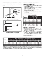
ELECTRICAL SPECIFICATIONS FOR HARD WIRING
Voltage
110-120 VAC, 60 Hz, 1 phase
Minimum Circuit Capacity
9A
Maximum Fuse or Circuit
Breaker Amps
16A
Minimum Wire Size AWG
14
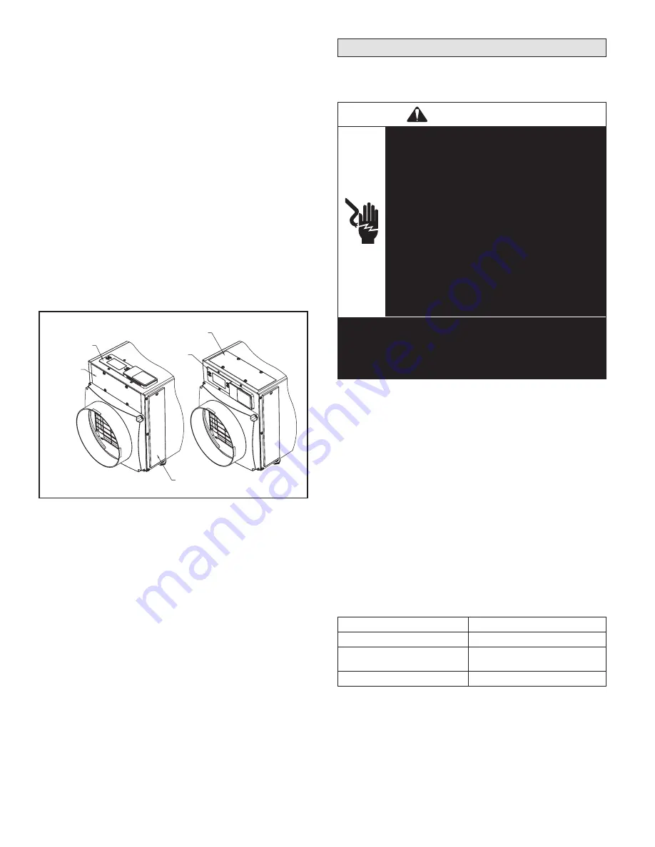
CONTROL LOCATION
The on-board control can be located on the top of the
dehumidifier or can be relocated to the front of the
dehumidifier if the control can not be seen/accessed in
the top orientation.
To move the control:
1. Remove the front control panel cover.
2. Remove the filter access door and filter.
3. Detach the on-board control by removing the four
(4) screws around the control.
NOTE:
Use one hand
to support the bottom of the on-board control when
removing.
4. Keep the control in the unit and relocate to the front
access hole.
5. Secure the control with the same four screws used to
attach the control to the top of the unit.
6. Secure the control panel cover to the top of the unit.
Figure 4. Control Location
CONTROL
PANEL
COVER
CONTROL
CONTROL
CONTROL
PANEL COVER
FILTER ACCESS DOOR
90-1884
4


