The ComfortSense
®
7000/7500 Thermostat, the iComfort
Wi-Fi
®
Thermostat, or the iComfort
®
S30 Thermostat (when
using an iComfort
®
enabled HVAC system) can be used as
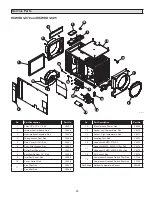
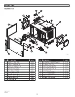
an external control, if used with a relay. The recommended
relay is Catalog # 69J79. See
Figures 18 & 19
for wiring.
The NC NO slide switch should remain in the NO position.
When an external control is enabled, “EXTERNAL” will be
displayed on the dehumidifier control. External controls are
recommended when the dehumidifier is installed in an attic
and is ducted to the HVAC system.
If an external control is used in a zoned application, it must
be located in the Primary Zone (refer to TWO ZONE –
PRIMARY AND SECONDARY zoned installation on page
15 for details).
NOTE: When using an external control, there is a 3
minute delay at start-up or whenever power is cycled
to the dehumidifier. As with any configuration, the
compressor has a 3 minute minimum on and off time.
NOTE:
Both the ComfortSense
®
7000/7500 Thermostat
and the iComfort
®
Thermostats use reverse logic for
dehumidification. There is 24VAC between the DH and
C terminals when there is no call for dehumidification.
Figures 18 & 19
show relay position when there is a call for
dehumidification and 0VAC between the DH and C terminals.
Figure 18. ComfortSense
®
7000/7500 Thermostat Wiring
Figure 19. iComfort
®
Thermostat Wiring
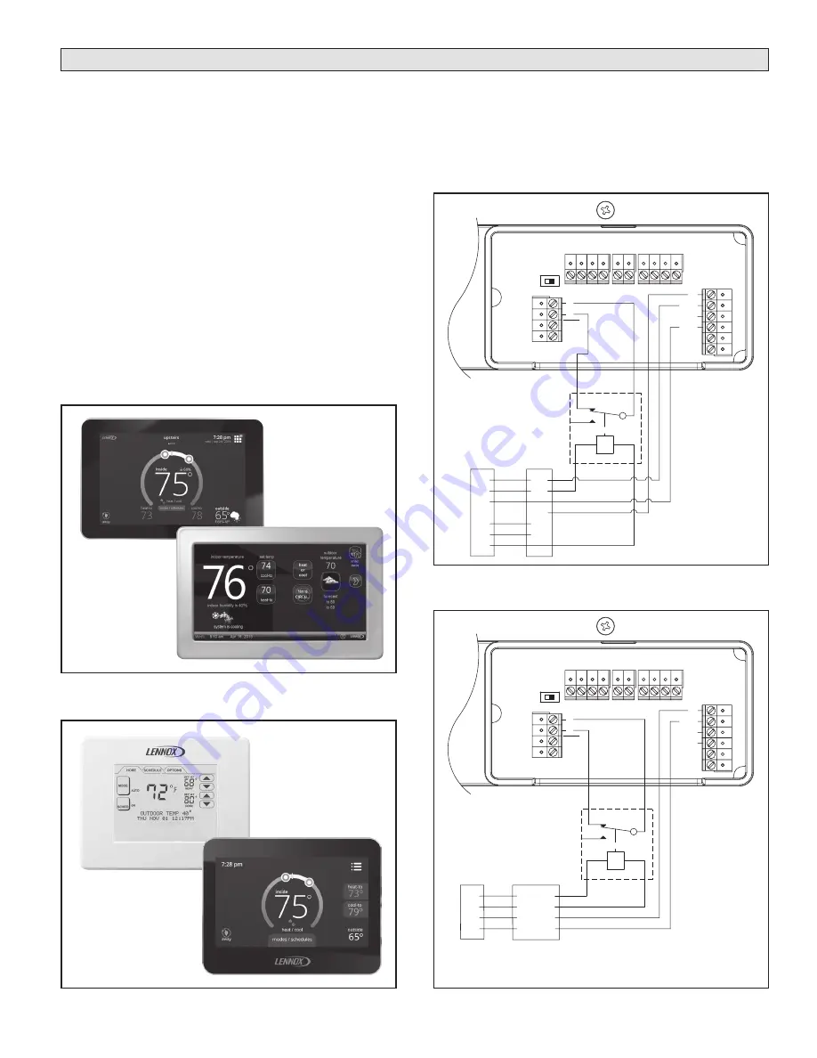
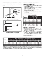
Figure 17. ComfortSense
®
Touchscreen Thermostats
Figure 16. iComfort
®
Thermostats
+ - A B ODT
FLOA
T
Switch
DH
DH
Gh
Rf
Cf
Gs
Y
W
HV
AC EQUIP
.
HVAC
Unit
NC NO
NC
NO
ComfortSense
®
7000/7500
Thermostat
SPDT RELAY
R
C
G
Y
W
R
C
G
DH
Y
W
+ - A B ODT
FLOA
T
Switch
DH
DH
Gh
Rf
Cf
Gs
Y
W
HV
AC EQUIP
.
DH
C
G
R
R
I+
I-
C
iComfort
Enabled
HVAC Unit
NC NO
NC
NO
R
I+
I-
C
iComfort
Thermostat
SPDT RELAY
90-1989
90-1979
Lennox Control
iComfort
®
S30
Thermostat
(Catalog # 12U67)
ComfortSense
®
7000 Touchscreen
Thermostat
(Catalog # Y2081)
iComfort Wi-Fi
®
Thermostat
(Catalog # 10F81)
ComfortSense
®
7500 Touchscreen
Thermostat
(Catalog # 13H14)
9


