44
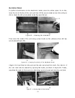
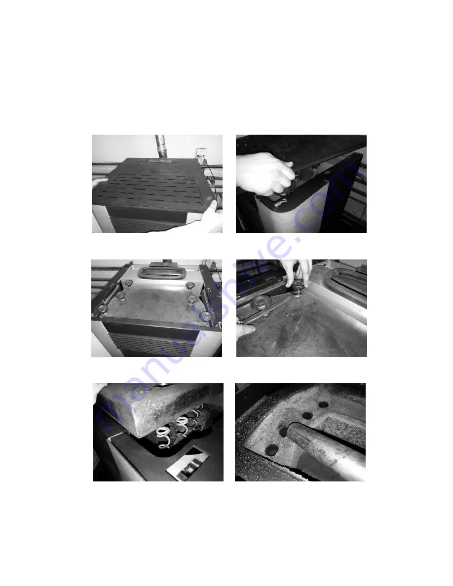
For the backboiler unit, the procedure involves cleaning the air flow pipes and
turbulators. To do this, open the lid on the top of the unit (Figure 51-a and b) and remove
the four sticks (Figure 51-c and 51-d). Then pull the turbulators up (Figure 51- e). A
vacuum cleaner must be used to clean this area (Figure 51-f) and the interior of the
pipes can be cleaned with a steel brush. The turbulators that are removed must also be
cleaned with a steel brush.
To reinstall the turbulators, execute in reverse the above procedure shown in the figures.
a)
b)
c) d)
e) f)
Figura 30 – Cleaning of gas passageways and turbulators
Summary of Contents for Douro 12kW
Page 13: ...12 a b ...
Page 50: ...49 ...
Page 51: ...50 ...
Page 52: ...51 ...
Page 58: ...57 18 Electrical Diagram of the Free Standing Fire Unit Figure 40 Electrical diagram ...
Page 70: ...69 21 Annexes 21 1 Flow chart Lighting ...
Page 71: ...70 ...
Page 72: ...71 Disabling ...


