46
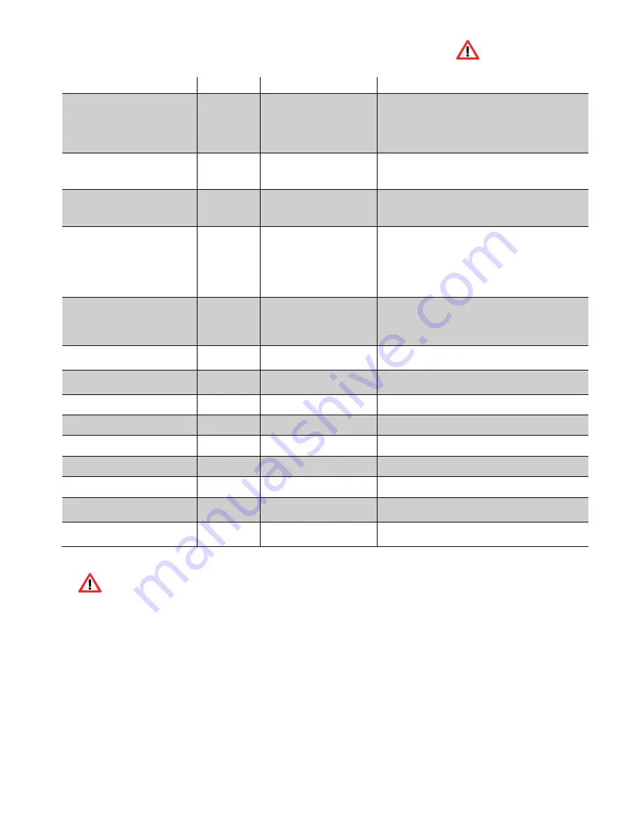
14. Alarm / Failure / Recommendation List
Table 2 – List of alarms
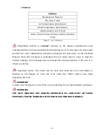
Important notice: when triggered, all the alarms above cause the machine to
shutdown. The alarm must be reset and the unit restarted. To reset the unit, press the
“On/Off” button for 3 to 4 seconds until the alarm sounds.
Alarm
Code
Troubleshooting
Ignition failure
A01
Maximum time 900 sec
- the worm drive channel is empty - restart the
unit
- resistance burnt
– replace resistance
- the burning basket has been incorrectly
installed
No flame or lack of
pellets
A02
Temperature under:
- 109.4ºF (43°C)
(backboiler model)
- Pellet reservoir is empty
Excess heat in the pellet
drum
A03
194ºF (90°C)
- the fan is not working
– call for assistance
- faulty thermostat - call for assistance
- machine with faulty ventilation
Excess fume temperature
A04
Over 446ºF (260°C)
(backboiler model)
- the fan is not working or is working at a low
power level - increase the level to the
maximum (if the problem persists, call for
assistance)
- Insufficient extraction
- Excess pellets
Pressure switch alarm
A05
The door is open, lack
of draught or extractor
fault for 120 sec
- close the door and clear the error message
on the faulty pressure regulator
- obstruction of the exhaust pipe or faulty
extractor
Air mass probe
A06
40 Ipm delta for 900
sec
- pipes with insufficient extraction or obstructed
pipes
The door is open
A07
Door open for 120
seconds
- close the door - clear the error message
Fume extractor is faulty
A08
Connection failure
- check connection
Fume probe failure
A09
Connection failure
- check connection
Pellet resistance error
A10
Connection failure
- check connection
Worm drive error
A11
Connection failure
- check connection
Pellet level alarm
A15
- check connection
Water pressure outside
operating range
A16
- check connection
Excess water
temperature
A18
- check connection
Summary of Contents for Douro 12kW
Page 13: ...12 a b ...
Page 50: ...49 ...
Page 51: ...50 ...
Page 52: ...51 ...
Page 58: ...57 18 Electrical Diagram of the Free Standing Fire Unit Figure 40 Electrical diagram ...
Page 70: ...69 21 Annexes 21 1 Flow chart Lighting ...
Page 71: ...70 ...
Page 72: ...71 Disabling ...


