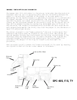
Trough flush piping
Some pulpers have a “feed tray” for feeding waste into the pulper, in which
case, the flush water is piped at the factory. Some models have a “feed
trough” which is commonly integrated into a stainless steel table or
dishwasher. In this case, the trough flush plumbing must be installed. This
connection is also made at the “end plate” behind the drive motor. The
trough flush location is labeled on the end plate. This connection is made
to a 1-½ inch female pipe thread. The 1-½ pipe diameter should be maintained
from the pulper to the trough end flush nozzle. Trough designs can vary and
there may be other flush nozzles that branch off from this 1 ½ trunk line.
Consult the final installation drawings to confirm the final trough and flush
design.
ELECTRICAL
This reference will describe the connection of the pulper junction box to the
pulper’s control panel.
The pulper junction box is located behind the pulper drive motor, and is
accessed by removing the junction box cover from the “end plate”, next to the
plumbing connections. The
specified
conduit between the pulper junction box
and the control panel is
1 ¼ inch flexible plastic conduit
known as Sealtite.
There is a penetration cut in the side of the junction box and is designed to
receive a 90 degree Sealtite connector. All junction box & control panel
wiring is to be contained within this 1 ¼ Sealtite. Also, there is a 3/8-
diameter polyethylene tubing, which carries air for the water level control
system. This piece of
tubing is also run inside this 1 ¼ Sealtite along with
the wiring.
This Sealtite can be run the entire distance from the pulper to
the control panel, or if desired, it can be run to a junction box and the run
can be completed with rigid conduit.
Within the conduit, there are control wiring and power wiring. The control
wiring carries the 120 VAC or 24 VDC control signals, while the power wiring
carries the 3-phase power to run the motors. All the control wiring should
be 18-gage wire. All the power wiring should be 12-gage wire.
The quantity and identification of power and control wire can vary from unit
to unit, but the following guideline is correct in all cases.
FOR EACH UNIQUE TERMINAL NUMBER IN THE PULPER JUNCTION BOX, THE
APPROPRIATE GAGE WIRE SHOULD BE PULLED, LABELED AND LANDED.
If there are multiple terminals with the same number in the junction
box, only one wire for that terminal need be pulled. For example, there will
be multiple terminals labeled #2. Only one #2 wire need be pulled, and can
be landed on any #2 terminal.
If desired or needed, these instructions can be confirmed on the final
installation drawings.
In most cases, you will have to wire the start/stop push button
station. (Refer to the sketch.) The push button station is wired to the
pulper junction box via half-inch sealtite. As always, confirm the exact
wiring with the FE drawing that came with the unit.


