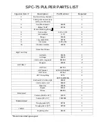
EXTRACTOR DRIVE MOTOR REMOVAL -
•
After turning the circuit breaker off, remove cover on drive motor junction box and
disconnect motor leads.
•
Remove conduit from motor junction box.
•
The drive motor (1) can be removed from the head assembly by removing four
screws (3 & 4).
EXTRACTOR SPEED REDUCER REMOVAL -
•
Remove bolt (6 & 7) and four machine screws (8, 9, and 10).
•
Loosen four set screws in collar of reducer (5) to free it from the screw shaft (19).
•
Access to the bottom two set screws can be gained by turning the reducer until
the set screws line up with the openings in the side of the reducer. The reducer
can now be lifted off the screw shaft.
EXTRACTOR SCREEN AND SCREW REMOVAL -
•
After removing four machine screws (12, 13, & 14), from head assembly (11) lift
head with screen (15) and screw assembly (19) attached, from the Hydra-
Extractor
shell (27).
•
By removing a machine screw (23, 24, 25), the plug cutter (22) can be removed
from the screw assembly.
•
Remove the screw assembly from the screen assembly by pulling the screw
assembly through the
bottom opening of the screen, while turning bottom of
screw counter-clockwise with a pipe wrench.
•
After removing the screw assembly, remove two button head machine screws
(16, 17, 18), from the screen and slip the screen from the head assembly.
EXTRACTOR BOTTOM PIN REMOVAL -
•
Remove six machine screws (44, 45, and 46).
•
The bottom pin plate (41) with bottom pin (39) attached can now be removed.
•
Remove screw (42 & 43). The bottom pin can now be separated from the bottom
pin plate.
Summary of Contents for SPC-75S
Page 12: ...Installation ...
Page 16: ...MOUNTING DETAIL OF TROUGH ...
Page 21: ...FOR REFERENCE ONLY ...
Page 22: ...Start Up ...
Page 26: ...Operation ...
Page 32: ...CLEANING YOUR SYSTEM ...
Page 38: ...MAINTENANCE ...
Page 49: ...TROUBLESHOOTING ...
Page 56: ...REPLACEMENT PARTS EXPLODED VIEWS ...
Page 57: ......
Page 60: ......
Page 62: ......


