


• Align the chain head (A) with the frame
fitting (B).
• Close the window by exerting a certain
amount of pressure and insert the safety
split pin (E).
• Connect the actuator to the mains supply as
shown in the enclosed wiring diagrams and in
compliance with safety standards.
• Run the actuator to the end of stroke to open
the window and close it again. This operation
tests that the actuator is working correctly and
that the window is closing properly.
Danger!
Danger of hands being crushed.
When the window is moving do not
insert your hand between the fixed
frame and the moving parts.
Checking the operating efficiency of the limit
switches of the Linkeo 2 actuator.
• The Linkeo 2 actuator is fitted with two limit
switches that stop opening and closing at the
beginning and the end of the stroke. It is
therefore necessary to ensure that the internal
microswitches disconnect the power supply to
the motor when the fully opened and fully
closed positions are reached.
The internal microswitches disconnect the
power supply to the motor when the fully
opened and fully closed positions are
reached. When the fully opened or fully closed
positions are reached, you will feel the motor
making the outer structure vibrate if you lay
your hand on it.
• If the motor does not cut out when the end of
stroke is reached, proceed as follows:
1) Disconnect the actuator from the power
supply.
2) Immediately contact SOMFY Technical-
Sales Department.
• If the window does not close correctly,
proceed as follows:
1) Remove safety split pin (E).
2) Use the control push-button to make the
actuator open and close completely.
3) Close the window by exerting a certain
amount of pressure.
4) Insert the safety split pin (E)
Warning!
The actuator is not a structural member
of the window. Mount the safety armsin
bottom-hung applications.
B
FITTING TO A HOPPER-FRAME
WINDOW
INSTRUCTIONS ON FITTING, USING AND
MAINTAINING THE ACTUATOR
Linkeo 2
A08
A09
4
Warning!
The plugs underneath must be left in
their housing to prevent the covers from
being moved.
• If the material of the sill enables it, fix the
actuator to the sill by inserting the screws (30)
(not supplied) and tightening them. The screws
will perforate the plastic plugs that have been
left in their housing. Otherwise, drill using the
four holes on the actuator as a drilling template,
insert the screws (30) (not supplied) and tighten.
• Close the screw holes by inserting the plugs
(D) on the side where the screws are inserted.
A06
A07
• Insert a screwdriver into the slits on the cover
and remove the plastic protective plugs (D).
Take care to remove only the protective plugs
on the side where the screws are inserted,
opposite to the actuator support surface.
A05
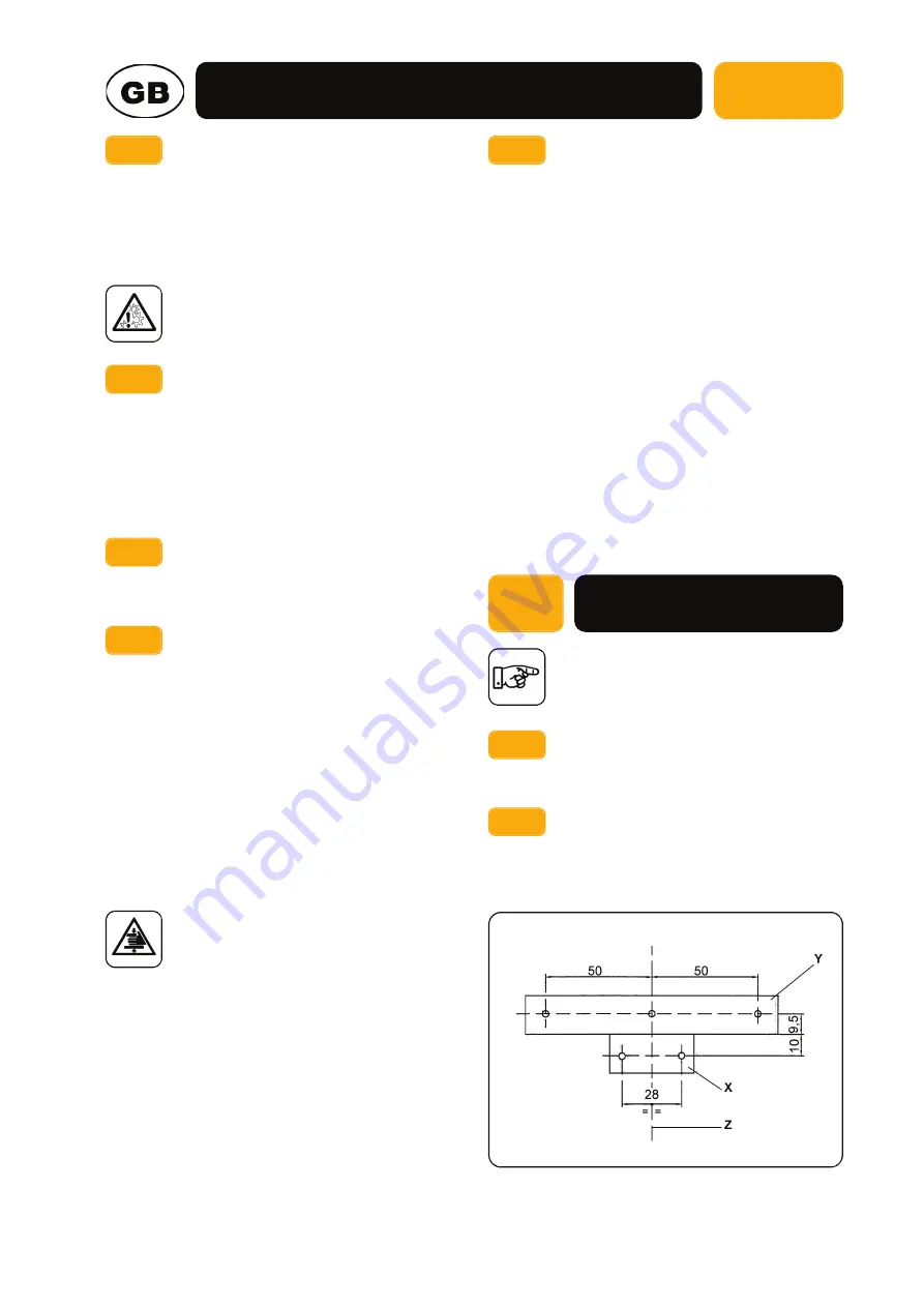
• Find and trace the centre line of the window
and the fixed frame.
• Drill holes in the places indicated on the
drawing using drill bits of the required
diameter, as per the following scheme:
B01
B02
Summary of Contents for Linkeo 2
Page 3: ...A04 A05 A06 A01 A02 A03 A A00 B A C E 1 2 3 1 2 3 AF 4 8 x 13 AF 3 5 x 16 M5 x 10...
Page 4: ...A07 A08 A09...
Page 5: ...B04 B05 B06 B01 B02 B03 B B00 2 3 4 AF 3 5 x 16 M5 x 10 AF 4 8 x 22 G A 4 F C 2 3...
Page 7: ...C04 C05 C06 C07 C08 C09...
Page 8: ...ENGLISH FRAN AIS DEUTSCH DUTCH ESPA OL 1 2 12 22 32 42...


