background image

www.somfy.com

SLIDYMOOVE


FR

Remplacement du boîtier électronique

EN

Replacing the electronic unit

PL

Wymiana modułu elektronicznego

5127569A

Summary of Contents for SLIDYMOOVE

Page 1: ...www somfy com SLIDYMOOVE FR Remplacement du boîtier électronique EN Replacing the electronic unit PL Wymiana modułu elektronicznego 5127569A ...

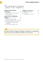
Page 2: ...Auto apprentissage de la course du portail 6 2 4 Mise en veille réveil de l électronique de commande 7 2 5 Déverrouillage verrouillage du moteur 7 Version originale du manuel Ce manuel décrit le remplacement du boîtier électronique de votre motorisation et sa mise en service Pour plus de détails sur le câblage le paramétrage et l utilisation de votre motorisation veuillez consulter le manuel d ins...

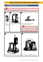
Page 3: ... 0 V Mettre l installation hors tension Dévisser puis enlever le capot du moteur Repérer le câble d alimentation 230V et les câbles des périphériques Tant qu ils ne sont pas rebranchés les fils des accessoires doivent rester isolés par exemple avec des dominos d électricien ou du scotch isolant pour éviter tout risque de court circuit 4 5 Installer et visser le nouveau boîtier électronique Clipser...

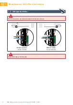
Page 4: ... ces opérations doivent se faire hors tension 5 5 6 6 START ART M1 M1 M2 M2 11 11 13 13 10 10 12 12 BATT BATT 7 7 FLASH 8 8 9 9 24V Marron Bleu 5 5 6 6 START ART M1 M1 M2 M2 11 11 13 13 10 10 12 12 BATT BATT 7 7 FLASH 8 8 9 9 24V Marron Bleu Moteur à gauche Vue de l intérieur Moteur à droite Vue de l intérieur Ne rien brancher sur la borne M2 ...

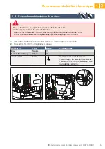
Page 5: ...ur fil Type Borne Commentaires Bleu Neutre 17 Marron Noir Rouge Phase 16 Jaune et Vert Terre Visser la cosse du fil de terre de l électronique la cosse du fil de terre de l alimentation et la rondelle éventail avec la vis de mise en terre 1 Raccorder le fil de terre fourni en haut à droite de l électronique de commande 2 Brancher les fils comme indiqué dans le tableau ANT ANT BUS BUS 1 1 3 3 2 2 4...

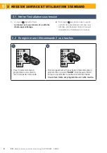
Page 6: ...c dans le manuel d installation et d utilisation du moteur 1 Le voyant clignote 2 fois Le moteur est sous tension et en attente d auto apprentissage 2 2 Enregistrer une télécommande 2 ou 4 touches 1 2 0 5s 0 5s Poser la télécommande à programmer sur la cible de l électronique de commande Faire un appui bref sur la touche de la télécommande à programmer Le voyant RADIO s allume puis s éteint lorsqu...

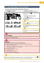
Page 7: ...e 2 fois Le portail est à mi course Le moteur est verrouillé voir page 7 IMPORTANT Si le portail est ouvert à la fin de l auto apprentissage 1 Effacer les réglages voir le manuel d installation et d utilisation du moteur 2 Mettre le moteur hors tension 3 Inverser les fils branchés sur les bornes 10 et 11 étiquette verte M1 de l électronique de commande voir Câblage du moteur page 3 4 Déverrouiller...

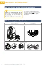
Page 8: ...ou pour vérifier modifier le paramétrage appuyer 2 secondes sur le bouton pour réveiller l électronique Lorsque l auto apprentissage a été effectué l électronique passe automatiquement en veille après 5 minutes d inactivité pour faire des économies d énergie En état de veille tous les voyants sont éteints 2 5 Déverrouillage verrouillage du moteur Déverrouillage Verrouillage SLIDYMOOVE 300 SLIDYMOO...

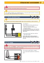
Page 9: ... commande à la fin de ce mouvement Fonctionnement avec des cellules photoélectriques Si les cellules sont occultées pendant la fermeture du portail le portail s arrête et se ré ouvre Ampoule 10 W 24 V MAXIMUM L utilisation d ampoule de puissance supérieure à 10 W 24 V peut provoquer des dysfonctionnements de la motorisation 3 2 Feu orange Fonctionnement du feu orange Le feu orange clignote pendant...

Page 10: ...2 2 4 4 5 5 6 6 START ART M1 M1 M2 M2 11 11 13 13 10 10 12 12 BATT BATT LIGHT LIGHT 230V 230V 15 15 17 17 14 14 16 16 7 7 FLASH 8 8 9 9 24V L L N N TX RX Pour plus de détails sur le câblage des accessoires veuillez consulter le manuel d installation et d utilisation de votre motorisation Accessoire incompatible avec une alimentation solaire ou ou ...

Page 11: ......

Page 12: ...mote control 5 2 3 Gate travel auto programming 6 2 4 Standby reactivation of the control electronics 7 2 5 Unlocking locking the motor 7 Translated version of the guide This guide describes how to replace and commission the electronic unit of your drive For more details concerning the wiring parameter settings and use of your drive please consult the installation and operating guide of your drive...

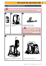
Page 13: ...tched off 1 2 3 1 ON 2 3 0 V Switch the installation off Unscrew and remove the motor cover Identify the 230V power supply cable and the peripherals cables Until they are reconnected the accessories wires must remain insulated for example with a screw terminal or insulating tape to avoid any risk of a short circuit 4 5 Install and screw the new electronic unit into place Clip the aerial on top of ...

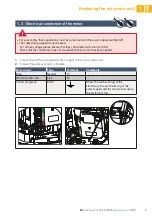
Page 14: ...rried out with the power supply switched off 5 5 6 6 START ART M1 M1 M2 M2 11 11 13 13 10 10 12 12 BATT BATT 7 7 FLASH 8 8 9 9 24V Brown Blue 5 5 6 6 START ART M1 M1 M2 M2 11 11 13 13 10 10 12 12 BATT BATT 7 7 FLASH 8 8 9 9 24V Brown Blue Motor on left hand side View from inside Motor on right hand side View from inside Connect nothing to terminal M2 ...

Page 15: ...ied Wire colour Type Terminal Comments Blue Neutral 17 Brown black red Live 16 Yellow and green Earth Screw the earth wire lug of the electronics the earth wire lug of the power supply and the star washer using the earthing screw 1 Connect the earth wire supplied to the top right of the control electronics 2 Connect the wires as shown in the table ANT ANT BUS BUS 1 1 3 3 2 2 4 4 5 5 6 6 START ART ...

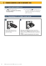
Page 16: ...lation and operating guide of the motor 1 The indicator flashes twice The motor is switched on and awaiting auto programming 2 2 Programming a 2 or 4 button remote control 1 2 0 5s 0 5s Position the remote control to be programmed on the control electronics target Briefly press the button on the remote control to be programmed The RADIO indicator light will come on then go out when you release the...

Page 17: ...tor light flashes twice The gate is at its mid point The motor is locked see page 7 IMPORTANT If the gate is open once auto programming is complete 1 Delete the settings see the installation and operating guide of the motor 2 Switch the motor off 3 switch the wires connected to terminals 10 and 11 green M1 label of the control electronics see Motor wiring page 3 4 Unlock the motor 5 Position the g...

Page 18: ...r to check modify the parameter setting press the button for 2 seconds to reactivate the electronics Once the auto programming process has been completed the electronics automatically switch to standby after 5 minutes of inactivity to save energy In standby mode all indicator lights are switched off 2 5 Unlocking locking the motor Unlocking Locking SLIDYMOOVE 300 SLIDYMOOVE 600 ...

Page 19: ...ronics once this movement is complete Operation with photoelectric cells If the cells are blocked when closing the gate the gate will stop and reopen 10 W 24 V bulb MAXIMUM use of a bulb with power greater than 10 W 24 V can cause drive malfunctions 3 2 Orange light Operation of the orange light The orange light flashes while the gate is moving For your safety these operations must be carried out ...

Page 20: ...BUS 1 1 3 3 2 2 4 4 5 5 6 6 START ART M1 M1 M2 M2 11 11 13 13 10 10 12 12 BATT BATT LIGHT LIGHT 230V 230V 15 15 17 17 14 14 16 16 7 7 FLASH 8 8 9 9 24V L L N N TX RX For more details concerning accessories wiring please consult the installation and operating guide of your drive Accessory not compatible with solar power or or ...

Page 21: ......

Page 22: ...oru przesuwania bramy 6 2 4 Ustawianie w tryb czuwania wzbudzenia elektronicznego układu sterowania 7 2 5 Odblokowanie zablokowanie napędu 7 Przetłumaczona wersja instrukcji Okablowanie akcesoriów 8 3 1 Fotokomórki 8 3 2 Pomarańczowe światło 8 3 3 Okablowanie pozostałych akcesoriów 9 Instrukcja ta opisuje sposób wymiany modułu elektronicznego Państwa zespołu napędowego oraz sposób jego uruchomieni...

Page 23: ... 2 3 1 ON 2 3 0 V Wyłączyć zasilanie instalacji Odkręcić i zdjąć pokrywę napędu Oznaczyć przewód zasilania 230V oraz przewody urządzeń zewnętrznych Przewody akcesoriów powinny pozostać zaizolowane np za pomocą kostek elektrycznych lub taśmy izolacyjnej dopóki nie zostaną ponownie podłączone aby uniknąć jakiegokolwiek ryzyka zwarcia 4 5 Zamontować i dokręcić nowy moduł elektroniczny Przypiąć antenę...

Page 24: ...onywać przy odłączonym zasilaniu 5 5 6 6 START ART M1 M1 M2 M2 11 11 13 13 10 10 12 12 BATT BATT 7 7 FLASH 8 8 9 9 24V Brązowy Niebieski 5 5 6 6 START ART M1 M1 M2 M2 11 11 13 13 10 10 12 12 BATT BATT 7 7 FLASH 8 8 9 9 24V Brązowy Niebieski Napęd z lewej strony Widok od wewnątrz Napęd z prawej strony Widok od wewnątrz Nie podłączać żadnego przewodu do zacisku M2 ...

Page 25: ...ienia Niebieski Neutralny 17 Brązowy Czarny Czerwony Faza 16 Żółty i zielony Uziemienie Wkręcić końcówkę przewodu uziemienia elektronicznego układu końcówkę przewodu uziemienia zasilania oraz podkładkę ząbkowaną za pomocą śruby uziemiającej 1 Podłączyć dostarczony przewód uziemienia w górnej prawej części elektronicznego układu sterowania 2 Podłączyć przewody jak wskazano w tabeli ANT ANT BUS BUS ...

Page 26: ...1 Kontrolka miga 2 razy Napęd znajduje się pod napięciem i w oczekiwaniu na automatyczne przyuczenie 2 2 Zapisywanie pilota zdalnego sterowania z 2 lub 4 przyciskami 1 2 0 5s 0 5s Położyć pilota zdalnego sterowania który ma być zaprogramowany na tarczy elektronicznego układu sterowania Wcisnąć krótko przeznaczony do zaprogramowania przycisk pilota zdalnego sterowania Kontrolka RADIO zapala się po ...

Page 27: ...miga 2 razy Bramaznajdujesięwpołowietoruprzesuwania Napęd jest zablokowany patrz strona 7 WAŻNE Jeśli brama jest otwarta na koniec procesu automatycznego przyuczenia 1 Wykasować ustawienia patrz diagnostyka w instrukcji montażu i obsługi napędu 2 Wyłączyć zasilanie napędu 3 Zamienić przewody podłączone do zacisków 10 i 11 zielona etykieta M1 elektronicznego układu sterowania patrz Okablowanie napę...

Page 28: ... w celu sprawdzenia zmiany ustawień należy nacisnąć i przytrzymać przez 2 sekundy przycisk aby wzbudzić elektroniczny układ 2 5 Odblokowanie zablokowanie napędu Odblokowanie Zablokowanie SLIDYMOOVE 300 SLIDYMOOVE 600 Po wykonaniu automatycznego przyuczenia elektroniczny układ przechodzi automatycznie w stan czuwania po 5 minutach braku reakcji aby zaoszczędzić energię W stanie czuwania wszystkie k...

Page 29: ...amy brama zatrzyma się i zacznie się ponownie otwierać Żarówka MAXIMUM 10 W 24 V Użycie żarówki o mocy powyżej 10 W 24 V może spowodować nieprawidłowe działanie zespołu napędowego 3 2 Pomarańczowe światło Działanie pomarańczowego światła Pomarańczowe światło miga gdy brama jest w ruchu Ze względów bezpieczeństwa czynności te należy wykonywać przy odłączonym zasilaniu Zaleca się wykonywanie automat...

Page 30: ...START ART M1 M1 M2 M2 11 11 13 13 10 10 12 12 BATT BATT LIGHT LIGHT 230V 230V 15 15 17 17 14 14 16 16 7 7 FLASH 8 8 9 9 24V L L N N TX RX W celu uzyskania szczegółowych informacji dotyczących okablowania akcesoriów należy zapoznać się z instrukcją montażu i obsługi Państwa zespołu napędowego Akcesoria niekompatybilne z zasilaniem z instalacji solarnej lub lub ...

Page 31: ......

Page 32: ...omfy Sp z o o Somfy LLC Russia Somfy Italia SRL Somfy España SA Somfy Portugal Somfy Hellas SA 0 820 055 055 0 15 la minute Forum d entraide forum somfy fr 07472 930 495 www somfy de 023 56 23 752 www somfy nl 02 712 07 70 www somfy be 44 0113 391 3030 www somfy co uk 900 20 68 68 www somfy es 808100153 www somfy pt 211 6000 222 www somfy gr 810377199 www somfy pl 8 800 555 60 70 www somfy ru diy ...

Reviews: