ASSEMBLY INSTRUCTIONS
A. Headrail Preparation
1. Cut or specify headrail width that is suitable for blind or shade application.
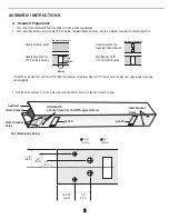
2. Cut or punch headrail to accomodate CTS 40 cradle. The illustrations below portray two different examples of headrail punches.
3. Drill the holes necessary for the motor and plug end and for access to the limit switch screws.
Headrail punched for
standard "Ladder Braids"
Modified punch for
CTS 40 cradle bearing
Top view of headrail
Headrail without punch
Headrail punched for
CTS 40 cradle bearing
Top view of headrail
1.5"
(38mm)
.787"
(20mm)
punch
punch
idler bracket
holes
limit switch
access holes (for non-RTS style motors)
See dimensions below
motor bracket
holes
motor bracket
headrail
1 1/8"
(28.5)
7/8"
(22.2)
1/2"
(12.7)
1 25/32"
(45.2)
1/2"
(12.7)
3/16"
(5 mm)
1/4"
(6 mm)
*SOMFY can provide Tool and Die (#1781099) to enable accurate punching for CTS components. Contact our sales group for pricing
and availability.
2


