61
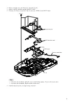
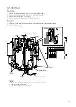
2-6. Front Assembly
Preparation
1. Remove the bottom harness guard. (Refer to “2-2. Bottom Harness Guard”.)
2. Remove the outside panel assembly. (Refer to “2-3. Outside Panel Assembly”.)
3. Remove the inside panel assembly. (Refer to “2-4. Inside Panel Assembly”.)
4. Remove the terminal assembly. (Refer to “2-5. Terminal Assembly”.)
Procedure
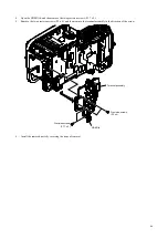
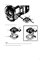
1. Disconnect the coaxial cable from the connector (J7381) on the CT-289 board.
Note
Pull out the coaxial cable perpendicularly to the connector.
2. Remove the two precision screws.
3. Release the hook and remove the WIFI holder assembly.
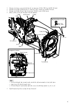
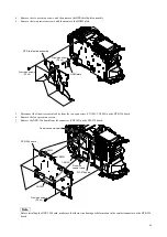
4. Remove the four precision screws, and then remove the rosette ring plate.
Note
•
Apply Loctite 243 before fixing the screws.
•
When installing the rosette ring plate, tighten the screws in the following sequence: (a), (b), (c), (d).
•
At the time of the installation, make sure that the coaxial cable is firmly on the hooks of the WIFI holder.
Precision screws
(P2 x 4)
Precision screws
(P2 x 4)
(a)
(c)
(d)
(b)
Precision screw
(P2 x 4)
Hole
Coaxial cable
CT-289 board
J7381
WIFI holder assembly
WIFI holder
Rosette ring plate
Coaxial cable
Arrangement of coaxial cable
Hooks
Hook
Loctite 243
Applying position of Loctite
More than
three threads


