INTRODUCTION
The Sonance iPort™ In-Wall Docking System allows an Apple iPod® to
become part of a whole-home audio system, and/or to be used as a source
in a variety of local audio systems. The iPort’s built-in IR emitters allow
users to operate the iPod via IR controllers (an optional 3rd-party IR receiv-
er required); the iPod can also be operated directly from its own controls.
The iPort supplies DC power to the iPod and recharges it while it is docked.
Before using the iPort Docking System please read and follow all of the
instructions in this guide carefully.
BOX CONTENTS
The Sonance iPort Docking System box should contain the following items:
iPort REAR-PANEL CONNECTIONS
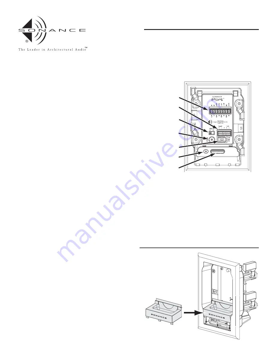
The Sonance iPort can supply balanced audio via the 8-pin connector, and
unbalanced audio via the stereo mini audio output in the base, and has a
5-pin connector that serves as an in-out loop for an optional low-level
volume control (to be introduced in 2005). See
Figure 1
for an explanation of
all the iPort’s connections.
INSTALLING THE iPort BASE CRADLE
The iPort can accommodate the 40GB Click Wheel iPod, 20GB Click
Wheel iPod and the iPod Mini. Each model requires a different base
cradle and back plate, all of which are included with the iPort.
Since the back plate covers the chassis mounting screws it won’t be
installed until after the iPort chassis has been mounted into a wall.
Before making connections and mounting the iPort into a wall, install the
appropriate base cradle (see
Figure 2
):
1. Find the base cradle for the model of iPod that will be used with the
iPort. The model designations (‘40GB’, ‘20GB’, ‘Mini’) are molded-into
the underside of each cradle.
2. Insert the base cradle into the iPort chassis with the rectangular cutout
centered over the multi-pin connector in the chassis base.
3. Tilt the cradle forward slightly and fit it down on the chassis base
by inserting 3 rectangular pegs on the front of the cradle into the
corresponding holes on the chassis.
4. Press on the cradle’s rear panel so the 2 rear rectangular pegs snap into place.
Note: Be careful not to damage the multi-pin connector in the iPort base.
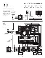
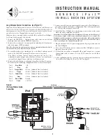
iPort SYSTEM CONNECTIONS
The Sonance iPort can be used where it is located some distance away
from the audio equipment (such as in a multi-zone system) with IR
control, or in a local-zone system where the audio equipment is located
close to the iPort and the iPod is controlled only from its front panel.
I N S T R U C T I O N M A N U A L
S O N A N C E i P o r t ™
IN-WALL DOCKING SYSTEM for iPod™
• One (1) Sonance iPort In-Wall
Docking System
• One (1) Cradle for 40GB Click
Wheel iPod.
• One (1) Back plate for 40GB click
Wheel iPod.
• One (1) Cradle for 20GB Click
Wheel iPod.
• One (1) Back plate for 20GB Click
Wheel iPod.
• One (1) Cradle for iPod Mini.
• One (1) Back plate for iPod Mini.
• One (1) iPort Wallplate.
• One (1) Audio cable (male stereo
mini-jack at both ends).
• One (1) IEEE 1394 to 30-pin
adapter cable.
• One (1) 15V DC regulated power
supply.
• One (1) Instruction manual.
• One (1) Mounting template.
Figure 2:
Installing the
Base Cradle
PATENT PENDING
8-Pin
Connector
5-Pin
Connector
Volume Control
IN/OUT Switch
Audio Input
IEEE1394
Connector
Audio Output
30-Pin Base
Connector
Figure 1:
iPort
Connections
8-Pin Connector:
Sends balanced left
& right channel audio to the iPort
Wallplate (the Wallplate unbalances
the audio before output); Receives
IR control signals and DC power
from the iPort Wallplate.
5-Pin Connector:
Sends and receives
900mV unbalanced left & right
channel audio to and from a Line
Level Volume Control.
Volume Control IN/OUT Switch:
Routes
the audio signal through the 5-pin
connector. (Left = Volume Control
OFF; Right = Volume Control ON.)
Audio Input:
Stereo mini jack receives
unbalanced audio from the iPort
Base Audio Output.
IEEE1394 Connector:
Sends DC power
to the iPort base via the 30-pin >
IEEE1394 adapter cable.
Audio Output:
Stereo mini jack
outputs 900mV unbalanced left &
right channel audio directly from
the iPod.
30-Pin Base Connector:
Receives DC
power from the iPort via the
30-pin > IEEE1394 adapter cable.
1


