3
I N S T R U C T I O N M A N U A L
S O N A N C E i P o r t ™
I N - W A L L D O C K I N G S Y S T E M
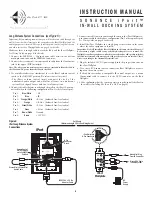
Controlling Volume in iPort Systems
Volume in a Local (single-zone) iPort system can be controlled by:
• At the local zone’s amplifier or with amplified volume controls (such as
the Sonance AVC100 series), depending on system configuration.
• Installing an (optional) Sonance low-level volume control in the iPort system.
Volume in a Long-Distance (multi-zone) iPort system can be controlled by:
• Volume controls in each local zone (determined by system configuration).
• Zone volume controls on the distributed audio system controller.
Note: The iPod volume control only controls the iPod’s headphone jack.
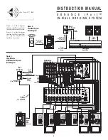
Local System Connections (see
Figure 5
):
Before making connections, run a length of CAT5 cable through the wall
from the iPort location to the iPort Wallplate location. (See
Wiring Guide
.)
1. Connect the IEEE1394 > 30-pin adapter cable between the bottom
multi-pin connector and the IEEE1394 connector.
2. Connect the stereo mini > stereo mini audio cable from the lower mini-
jack (Audio Output) to the upper mini jack (Audio Input).
Note: The above two connections are necessary to carry audio from the iPod to
the iPort, and DC power from the iPort to the iPod.
3. Connect the CAT5 cable to the iPort’s 8-pin connector block in the
following configuration (Pin 1 is the left-most pin):
Pin 1:
Blue/White
– IR
Pin 2:
Blue
+IR
Pin 3:
Orange/White
–R Out (balanced line-level audio)
Pin 4:
Orange
+R Out (balanced line-level audio)
Pin 5:
Green/White
–L Out (balanced line-level audio)
Pin 6:
Green
+L Out (balanced line-level audio)
Pin 7:
Brown/White
Ground
Pin 8:
Brown
+15V DC
Note: you can connect an additional (optional) local IR controller to Pins 1 and 2.
(IR Data & Ground) in parallel with the CAT5 wire connections.
4a. If the system is using Sonance low-level volume control, use a small
screwdriver or similar tool to set the iPort’s Volume Control switch to
the right (
ON
) position (
Volume control in system
).
4b. Use 5-conductor twin-shielded wire (such as Sonance part# 91874, colors
listed below) to connect the volume control to the iPort 5-pin
connector block in the following configuration (Pin 1 is the left-most pin
on the iPort; Pin 1 is the bottom pin on the volume control):
Pin 1:
Black
R ch line-level audio from volume control to iPort
Pin 2:
White
L ch line-level audio from volume control to iPort
Pin 3:
Bare Wire
Ground
Pin 4:
Red
R ch line-level audio from iPort to volume control
Pin 5:
Green
L ch line-level audio from iPort to volume control
Note: Do NOT use CAT5 wire to make these connections. This wire carries high-
impedance unbalanced line-level audio and must be twin-shielded to avoid noise.
A standard stereo RCA audio cable with the ends removed will work for this
application.
5. Connect the CAT5 cable to the iPort Wallplate’s 8-pin connector block
in the above configuration (Pin 1 is the top-most pin).
6. Install the iPort Wallplate in a single-gang electrical box in the room
where the audio equipment is located.
Important: Do NOT install the iPort Wallplate in the same electrical box as AC
house wiring, a light switch or any other high-voltage device or control. The
Wallplate can share gang boxes with other controls such as A/B speaker switches,
infrared receivers and volume controls, if these other devices are rated as Class 2
devices according to the National Electrical Code.
7. Plug the included DC power supply into the proper connector on the
iPort Wallplate.
8. Use a stereo RCA audio cable to connect the iPort Wallplate to a source
input on the audio system.
9. After confirming that the system operates properly, install the iPort in
the wall (see
Installation in a Wall
).
PATENT PENDING
Green
Red
Bare Wire
White
Black
5
4
3
2
1
IEEE1394 > 30-Pin
Adapter Cable
Stereo Mini > Stereo Mini
Audio Cable
8-Pin
Connector Block
5-Pin
Connector
Blocks
iPort
Wallplate
iPort
DC
Power
Supply
Stereo
RCA Cable
To Local
Audio System
Volume Control
ON/OFF Switch
Cat5 Cable (see Wiring Guide)
iPort Wallplate
8-Pin Connector
Low-Level
Volume
Control
(optional)
Sonance
91874
Cable
+IR (Data)
–IR (Gnd)
Input from
Local IR Controller
(optional)
Volume Contr
5-Pin
Connector
Figure 5:
iPort Local System
Connections


