INSTALLING THE iPort IN A WALL
The Sonance iPort features an integral RotoLock® mounting system for quick
mounting directly into existing walls. Once the hole is cut and the cables are
run (see
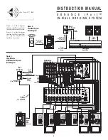
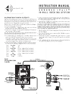
iPort System Connections
and
iPort Wiring Guide
), you can install the
iPort in a matter of seconds.
1. Determine the location for the iPort.
2. Perform an obstruction survey to be certain that there are no studs,
conduit, pipes, heating ducts or air returns that will interfere with the iPort.
Note: You can mount the iPort directly next to wall studs on either side (see Step 9).
3. The iPort cutout is 4
1
/
8
” (105mm) wide x 5
7
/
8
” (150mm) high. There
also must be at least 3” (76mm) depth within the wall cavity for the
iPort and its connections.
4. Find the cutout template provided in the iPort packaging. Position the
template where the iPort is to be located and pencil an outline on the wall.
• If you are unsure about obstructions, drill a small hole in the center of
the outline and insert a coat hanger wire into the hole to
feel-around for possible obstructions.
5. Cut the opening using a drywall saw.
6. Make all cable connections according to
System Connections
, above.
Double-check that all the connections are correct.
7. Insert the iPort into the opening in the wall.
Note: The RotoLock system can accommodate a maximum wall
material thickness of 1
3
/
8
”.
8. Tighten the four RotoLock screws on the iPort chassis (2 on each side).
The RotoLock clamps will automatically rotate into position and begin
clamping the iPort.
• When you notice resistance on the four screws the iPort has been
clamped successfully.
Important: Always use low-torque settings — NEVER over-tighten.
9. If there are wall studs up against either side of the iPort that prevent the
RotoLock clamps from operating, secure the iPort by driving 1½” #6
drywall screws (not provided) through the angled holes on the sides of
the chassis and into the wall studs.
Important: Always use low-torque settings — NEVER over-tighten.
10. Install the appropriate back plate. (The model designations (‘40GB’,
‘20GB’, ‘Mini’) are molded-into the rear of each back plate.)
• Insert the hooks at the bottom of the back plate into the slots at the
bottom of the opening in the iPort chassis. Rotate the back plate up
into the chassis so that the locking tabs at the top of the back plate
snap into place in the chassis.
• To remove the back plate, pull-down on the locking tabs, rotate the
plate forward and lift it out of the chassis.
• To remove the base cradle, insert a small screwdriver behind the
left side of the cradle’s rear panel and twist it slightly until the left
rear peg pops out. Repeat for the right rear peg, then lift the base
cradle out of the iPort chassis.
I N S T R U C T I O N M A N U A L
S O N A N C E i P o r t ™
I N - W A L L D O C K I N G S Y S T E M
Step 6
Step 7
RotoLock
screws
Step 8
If Next
to Stud,
Insert
1½" #6
Drywall
Screws
Here
Step 9
Insert Hooks
in Slots and
Secure Top of
Plate with Tabs
Step 10
PATENT PENDING
Wall
Stud
1½" #6
Drywall Screw
Insert
screwdriver
here
Removing the
base cradle
6


