5
NOTE: DO NOT PLUG THE POWER CORD INTO A POWER CONDITIONER
OR UPS SYSTEM.
Audio Connections
Your Sonance Cabinet Subwoofer has flexible connections that let
you use it in a wide variety of audio system configurations
(see Figure 2).
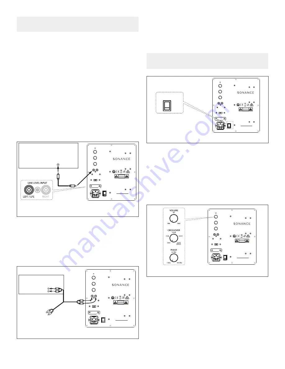
Line Level
You can connect the subwoofer’s line level input to a surround
processor or receiver’s line-level dedicated subwoofer LFE output
or a stereo preamp/integrated amplifier’s left and right variable main
outputs.
Connect the processor’s dedicated subwoofer output to the left
line level input jack labeled LEFT/LFE. If you are installing two
subwoofers in the system, use a ‘Y’ connector to connect both
subwoofers to the processor’s subwoofer output.
Option 2
Stereo preamp/power amp combination or an integrated
amplifier with preamp out jacks (see Figure 4).
Connection Examples
Follow the connection example that best describes your audio
system. The examples are listed in descending order of preference,
with the most ideal method presented first.
Option 1
Surround sound processor, surround sound receiver, or stereo
preamp with a dedicated subwoofer output (see Figure 3).
LFE
SUBWOOFER
OUTPUT
Surround
Processor/Receiver
Sonance
Subwoofer
AUDIO CABLE
STATUS
LINE LEVEL INPUT
VOLUME
MIN
MAX
CROSSOVER
50 HZ
250 HZ
150 HZ
75HZ
200 HZ
BYPASS
0 DEG
180 DEG
90 DEG
PHASE
RIGHT
LEFT / LFE
GROUND LIFT
GROUNDED
ISOLATED
100 -120V
220 – 240V
FUSE T4 AL / 250 VAC
AC 100-120V ~ 60Hz
AC 220-240V ~ 50Hz
ON
OFF
POWER
S/ N
MADE IN CHINA
This device complies with part 15 of the FCC
Rules.
Operation is subject to the following two
conditions:
(1) This device may not cause harmful
interference.
(2) This device must accept any interference
received, including interference that may cause
undesired operation.
FCC COMPLIANCE NOTICE
CAUTION
RISK OF ELECTRIC SHOCK DO NOT OPEN
RISQUE DE CHOC ELECTRONIQUE NE PAS OUVRIR
AVIS
GMA-503573-EA
MS10SUB
MAIN
OUTPUTS
Preamp/Integrated Amp
L
R
AUDIO CABLE
Sonance
Subwoofer
TO AMP
Figure 3: Connecting to a Surround
Processor’s Subwoofer Output
Figure 4: Connecting Between a Stereo Preamp/Integrated Amp
Connect the preamp/integrated amplifier’s left and right main
outputs to the subwoofer’s line level input jacks.
Figure 5: Subwoofer Adjustments
Sonance
Subwoofer
STATUS
LINE LEVEL INPUT
VOLUME
MIN
MAX
CROSSOVER
50 HZ
250 HZ
150 HZ
75HZ
200 HZ
BYPASS
0 DEG
180 DEG
90 DEG
PHASE
RIGHT
LEFT / LFE
GROUND LIFT
GROUNDED
ISOLATED
100 -120V
220 – 240V
FUSE T4 AL / 250 VAC
AC 100-120V ~ 60Hz
AC 220-240V ~ 50Hz
ON
OFF
POWER
S/ N
MADE IN CHINA
This device complies with part 15 of the FCC
Rules.
Operation is subject to the following two
conditions:
(1) This device may not cause harmful
interference.
(2) This device must accept any interference
received, including interference that may cause
undesired operation.
FCC COMPLIANCE NOTICE
CAUTION
RISK OF ELECTRIC SHOCK DO NOT OPEN
RISQUE DE CHOC ELECTRONIQUE NE PAS OUVRIR
AVIS
GMA-503573-EA
MS10SUB
ON
OFF
POWER
POWER SWITCH
Power On/Off
Once the subwoofer is properly connected for power and signal,
engage the POWER switch from OFF to ON (see Figure 5).
NOTE: NO SIGNAL WILL BE PASSED IF THE POWER SWITCH IS NOT
PROPERLY SELECTED.
Subwoofer Adjustments
Volume Adjustments
The VOLUME control sets the subwoofer’s volume output. When
setting the subwoofer’s volume control by ear, try to find a volume
setting where the bass sounds balanced on both music and films.
Listen to several different music recordings and film soundtracks
that contain strong bass passages and try to find a setting for the
volume control that doesn’t over-emphasize the bass or make it
sound weak (see Figure 6).
The most accurate way to set the volume control is with calibrated
test noise or test tones and a sound-pressure level (SPL) meter
or real time analyzer. There are several CDs and DVDs that
contain subwoofer test signals. If you use an SPL meter, set the
subwoofer’s volume control so that it plays at the same volume as
the system’s other speakers.
Figure 6: Subwoofer Adjustments
STATUS
LINE LEVEL INPUT
VOLUME
MIN
MAX
CROSSOVER
50 HZ
250 HZ
150 HZ
75HZ
200 HZ
BYPASS
0 DEG
180 DEG
90 DEG
PHASE
RIGHT
LEFT / LFE
GROUND LIFT
GROUNDED
ISOLATED
100 -120V
220 – 240V
FUSE T4 AL / 250 VAC
AC 100-120V ~ 60Hz
AC 220-240V ~ 50Hz
ON
OFF
POWER
S/ N
MADE IN CHINA
This device complies with part 15 of the FCC
Rules.
Operation is subject to the following two
conditions:
(1) This device may not cause harmful
interference.
(2) This device must accept any interference
received, including interference that may cause
undesired operation.
FCC COMPLIANCE NOTICE
CAUTION
RISK OF ELECTRIC SHOCK DO NOT OPEN
RISQUE DE CHOC ELECTRONIQUE NE PAS OUVRIR
AVIS
GMA-503573-EA
MS10SUB
Sonance
Subwoofer


