SONANCE • 212 Avenida Fabricante • San Clemente, CA 92672
Tech Support (800) 582-0772 www.sonance.com
©2002 All rights reserved.
Pg 2
33-1379 4.02
EQUIPMENT CABINET, CLOSET, ETC.
+12VDC
GND
GND
SIGNAL
120 V AC
(Unswitched)
IR Sensor
Window
CB1
Connecting Block
PS1
Power Supply
CR1
IR Receiver
VE1
Emitter
VE2
Dual Emitter
VE2
Dual Emitter
Satellite Receiver
Hand Held
Remote
AV Receiver
DVD
EMITTERS
PWR
IR
RCVR
CB1
ONE ZONE
CONNECTING BLOCK
CONNECTING THE EMITTERS
• Simply insert the mono mini plug of the
VE1
and
VE2
emitters into the "EMITTERS" or
"OUT" jacks on any of the Sonance Connecting Blocks or Controllers.
• CAUTION: DO NOT plug emitters into the IN/OUT or HIGH OUT jacks on the
CB1
and
ACB1 Connecting Blocks. To do so will destroy the emitters!
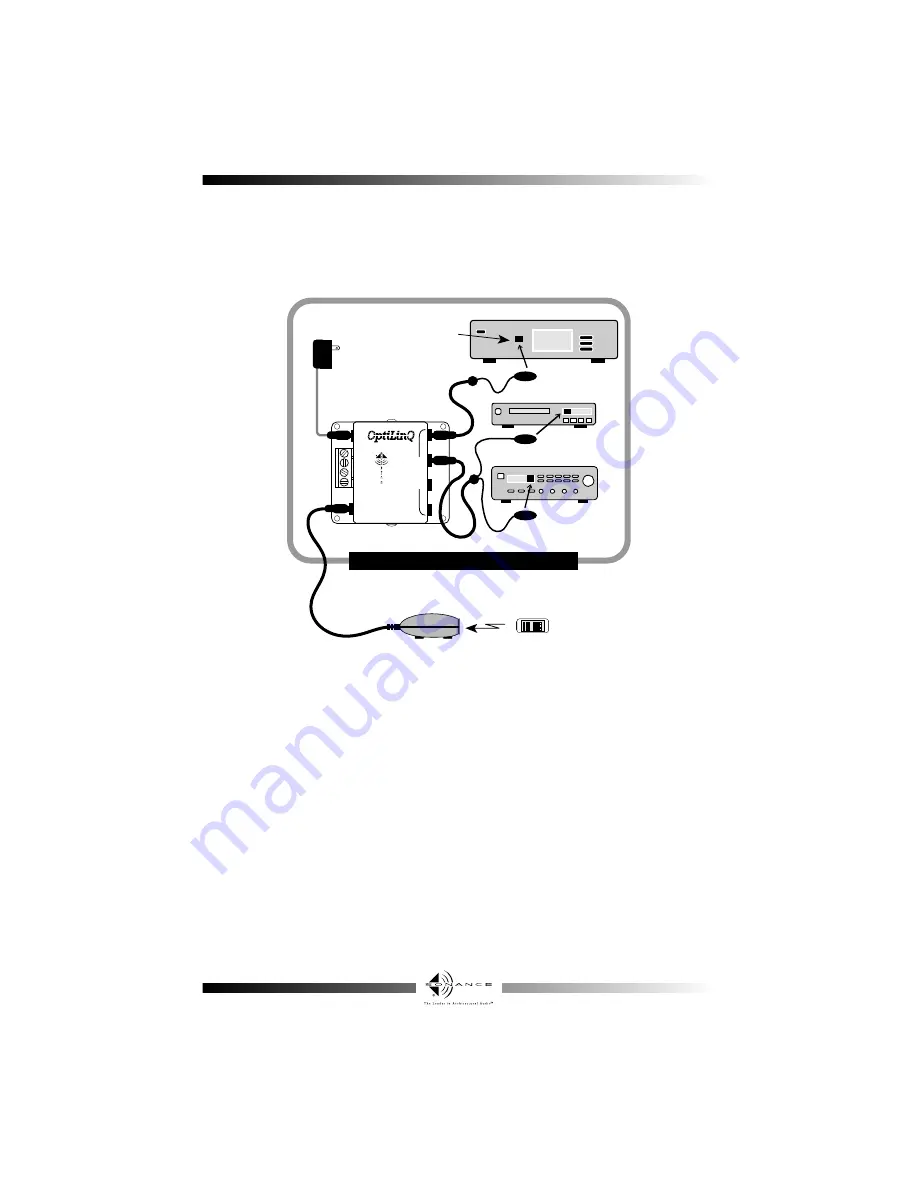
• The following diagram illustrates a typical basic system using the
VE1
and
VE2
emitters.
• The
VE2
is designed to control two devices. If only one is to be controlled, hide the extra
emitter behind the equipment. It may be used in the future if an extra device is added.
• DO NOT CUT the extra emitter wire in an attempt to remove it. The two emitters are wired
in series. Cutting or removing one emitter will prevent the other from working.
• These visible emitters may also indicate the presence of stray IR or RF interference by
randomly blinking when no IR control signal is being sent. Reposition the IR receiver or the
interfering source to eliminate or reduce the random blinking. The more the random
blinking is reduced, the better the system will function.
• If the emitter glows red constantly, the signal line is shorted to “+12VDC” or a constant
noise, like florescent lights are present near the IR receiver.


