Lodestar Hardware
Manual
Document Ref: UM-8084-101
Issue: A– Rev 8
© Sonardyne International Limited 2013
30
5.7 NMEA Connections to Listening Equipment
It is possible to connect a single Lodestar to more than one listening unit so that,
with Lodestar transmitting multiple NMEA sentences, each listener selects the
sentences they require and ignores all others.
Connection
arrangements
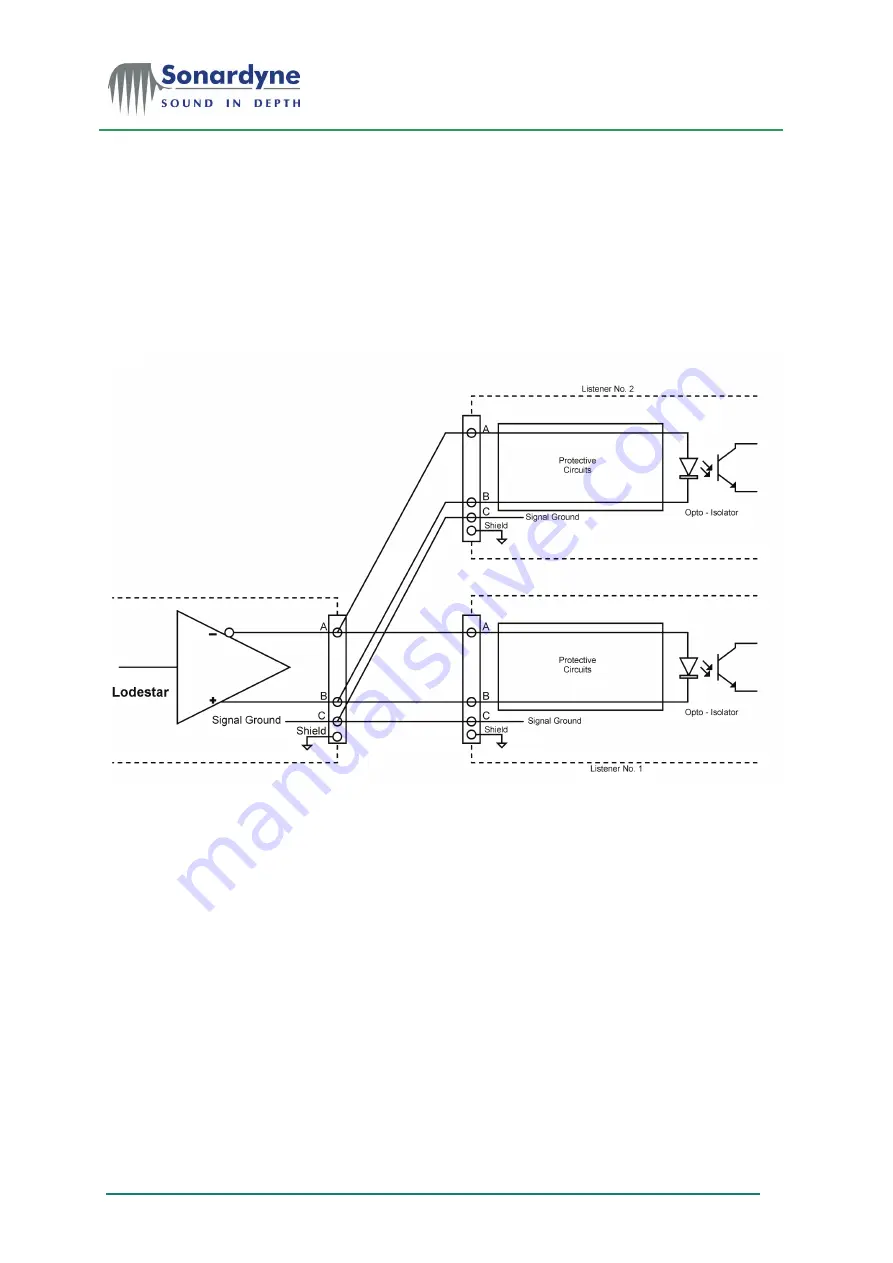
When used in this way, interconnections are through a two-conductor, shielded
twisted pair as shown in Figure 10.
Figure 10 – Listener receiving circuit
Receive circuits Multiple listeners can be connected to a single transmitting Lodestar. The listener
receive circuit must include an opto-isolator and protective circuits that limit
current, and protect against reverse bias and power dissipation at the opto-diode
as shown above.
The receive circuit must be designed for operation with a minimum differential
input voltage of 2.0 V and must not take more than 2 mA current from the line at
that voltage.
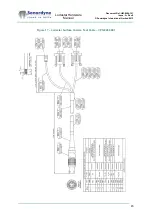
In the arrangement shown in Figure 17, all signal line A connections must be
connected to the listener device A connections, and signal B connections
connected to listener B connections. The shields of all listener cables should be
connected only to the Lodestar chassis—NOT to the listening device.
Within each listener there must be no direct electrical connection between signal
line A, the return line B, the shield, and the vessel’s ground or power lines.
Signal state
definitions
The idle, marking, logical 1, OFF or stop bit states are defined by a negative
voltage on line A with respect to line B.
The active, spacing, logical 0, ON or start bit states are defined by a positive
voltage on line A with respect to line B.


