background image

CMM-30 – MANUAL DE USO 

90 

5.2 

Medición de frecuencia  

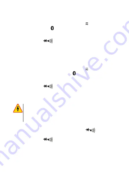
Para realizar la medición de frecuencia hay que: 

  poner el conmutador rotativo en 

la posición

 V

Hz%


pulsar el botón

 MODE 


hasta que el símbolo

 Hz

 aparezca en la 

pantalla, 


conectar el cable negro de medición a la toma 

COM

, el cable rojo 

a la toma 

V

ΩHz%


CAP ºC ºF

  poner las p

untas de las sondas en los puntos de la medición, 


leer el resultado de la medición en la pantalla. 

5.3 

Medición  %  del  ciclo  de  trabajo  (coeficiente  de 
relleno de impulso) 

Para realizar la medición hay que: 


poner el conmutador rotativo en la posición

 V

Hz%


pulsar  brevemente  el  botón

  MODE 


hasta  que  el  símbolo 

%


aparezca en la pantalla, 


conectar el cable negro de medición a la toma 

COM

, el cable rojo 

a la toma 

V

ΩHz%


CAP ºC ºF

  poner las puntas de las 

sondas en los puntos de la medición, 


leer el resultado de la medición en la pantalla. 

5.4 

Medición de resistencia 


ADVERTENCIA 


No  realice  mediciones  en  el  circuito  que  esté  bajo 
tensión. Antes de la medición desconectar la tensión y 
descargar los condensadores. 


Para realizar la medición de la resistencia hay que: 


poner el conmutador rotativo en la posición


Ω


conectar el cable negro de medición a la toma 

COM

, el cable rojo 

a la toma 

V

ΩHz%

 CAP 

ºC ºF


poner  las  puntas  de  las  sondas  en  los  puntos  de  medición;  es 
mejor  desconectar  un  lado  del  elemento  de  prueba  para  que  el 
resto del circuito no distorsione la lectura de la resistencia, 


leer el resultado de la medición en la pantalla. 

Summary of Contents for CMM-30

Page 1: ...INSTRUKCJA OBS UGI 1 USER MANUAL 38 MANUAL DE USO 75 CMM 30 v1 03 26 08 2019...

Page 2: ......

Page 3: ...1 INSTRUKCJA OBS UGI MULTIMETR PRZEMYS OWY CMM 30 Wersja 1 03 26 08 2019...

Page 4: ...es w funkcja REL umo liwiaj ca dokonywanie pomiar w wzgl dnych funkcja MAX MIN AVG umo liwiaj ca wy wietlanie warto ci mak symalnej minimalnej i redniej funkcja PEAK umo liwiaj ca wy wietlenie warto c...

Page 5: ...3 Pomiar cyklu roboczego wsp czynnika wype nienia impulsu 16 5 4 Pomiar rezystancji 16 5 5 Test ci g o ci obwodu 17 5 6 Test diody 17 5 7 Pomiar pojemno ci 18 5 8 Pomiar pr du 19 5 8 1 Zakres 10 A 19...

Page 6: ...nie wy wietlacza 25 6 7 Automatyczne wy czenie urz dzenia 25 7 Wymiana baterii i bezpiecznik w 26 8 Utrzymanie i konserwacja 28 9 Magazynowanie 29 10 Rozbi rka i utylizacja 29 11 Za czniki 30 11 1 Dan...

Page 7: ...ych problem w s poprzedzone symbolem OSTRZE ENIE Miernik CMM 30 jest przeznaczony do pomiar w pr du oraz napi cia sta ego i przemiennego cz stotli wo ci rezystancji pojemno ci a tak e test w diod i ci...

Page 8: ...cza maksymalnych limit w sygna u wej ciowe go w trakcie pomiar w napi cia nie nale y prze cza urz dzenia w tryb pomiaru pr du lub rezystancji i odwrotnie w przypadku zmiany zakres w zawsze nale y od c...

Page 9: ...A mA DC 800 mA DC AC RMS A AC A DC 10 A DC AC RMS Rezystancja ci g o test diody pojemno cz stotli wo cykl roboczy 600 V DC AC RMS 2 2 Symbole bezpiecze stwa Niniejszy symbol umieszczony w pobli u inn...

Page 10: ...k funkcyj ny w po o eniu OFF wy czony Przyrz d wyposa ono w funkcj automatycznego wy czania po up ywie ok 15 minut braku dzia ania Aby ponownie w czy miernik ustawi prze cznik funkcyjny do po o enia O...

Page 11: ...o liwo e w pewnych niskich zakresach napi cia zmiennego lub sta ego gdy do miernika nie pod czono przewod w pomiarowych na ekranie pojawi si przypad kowe i zmienne odczyty Jest to normalne zjawisko kt...

Page 12: ...CMM 30 INSTRUKCJA OBS UGI 10 4 Opis funkcjonalny 4 1 Gniazda i funkcje pomiarowe...

Page 13: ...W czanie wy czanie komunikacji bezprzewodowej Bluetooth nacisn i przytrzyma Prze cznik obrotowy Wyb r funkcji A pomiar pr du sta ego i przemiennego do 600 0 A mA pomiar pr du sta ego i przemiennego do...

Page 14: ...e wyniku pomiaru na wy wietlaczu nacisn kr tko Pod wietlenie wy wietlacza nacisn i przytrzyma Przycisk PEAK Tryb latarki nacisn kr tko Wy wietla warto szczytow mierzonego sygna u naci sn i przytrzyma...

Page 15: ...Fahrenheita Celsjusza n m k M Przedrostek wielokrotno ci jednostki pomiaru OL Przekroczenie zakresu pomiaru Tryb automatycznego wy czenia Bateria roz adowana AUTO Automatyczne ustawianie zakresu HOLD...

Page 16: ...starczonych przez niego przewod w OSTRZE ENIE Pod czanie nieodpowiednich przewod w grozi pora eniem pr dem elektrycznym lub mo liwo ci wyst pienia b d w pomiarowych Sondy pomiarowe wyposa one s w doda...

Page 17: ...i 0 V przy jednoczesnej obecno ci napi cia w gnie dzie Przed orzeczeniem o braku napi cia w gnie dzie na le y upewni si e ko c wki sondy dotykaj meta lowych styk w wewn trz gniazda UWAGA Nie mierzy na...

Page 18: ...omentu wy wietlenia symbolu na wy wietlaczu pod czy czarny przew d pomiarowy do gniazda COM a czer wony do gniazda V Hz CAP C F przy o y ostrza sond do punkt w pomiarowych odczyta wynik pomiaru na wy...

Page 19: ...przy warto ciach rezystancji poni ej ok 30 5 6 Test diody OSTRZE ENIE Nie wolno dokonywa pomiar w w obwodzie b d cym pod napi ciem Przed pomiarem od czy napi cie i roz adowa kondensatory Nie wolno bad...

Page 20: ...ar w wyj przewody z gniazd pomiarowych miernika 5 7 Pomiar pojemno ci OSTRZE ENIE Ryzyko pora enia pr dem Nale y od czy zasilanie od badanego kondensatora i roz adowa wszystkie kondensatory przed jaki...

Page 21: ...y wykona pomiar pr du nale y ustawi prze cznik obrotowy w pozycji 10A nacisn przycisk MODE w celu wy wietlenia na wy wietlaczu symbolu je li mierzony b dzie pr d przemienny je li mierzony b dzie pr d...

Page 22: ...w DC pod czy czerwon sond do bieguna dodatniego w czy zasilanie obwodu odczyta wynik pomiaru na wy wietlaczu 5 9 Pomiar temperatury Aby wykona pomiar na le y ustawi prze cznik obrotowy w pozycji C F...

Page 23: ...omiar przez co jest on bardziej dok adny i rzetelny Napi cia takie mog wyst powa w wyniku pojemno ciowego sprz enia pomi dzy przewodami pod napi ciem a nieu ywanymi przewodami wyst puj cymi w s siedz...

Page 24: ...rowany Od tej pory odczyty b d przedstawia jako stosunek warto ci mierzonej do warto ci odniesienia Aby wy czy tryb nacisn przycisk REL AC DC Wy wietlany g wny wynik to r nica warto ci odniesienia odc...

Page 25: ...dotychczasowych odczyt w pomiaru Symbol MIN miernik wy wietla najmniejsz warto spo r d dotychczasowych odczyt w pomiaru Symbol AVG miernik wy wietla redni warto spo r d dotychczasowych odczyt w pomiar...

Page 26: ...Funkcja dost pna tylko podczas pomiaru napi cia i pr du AC W czasie gdy funkcja PEAK jest aktywna nie dzia a au tomatyczne dobieranie zakres w dlatego zaleca si uru chamia funkcj dopiero po pod czeni...

Page 27: ...ni cie i przytrzymanie przycisku HOLD przez 2 se kundy powoduje w czenie lub wy czenie funkcji pod wietlenia wy wietlacza 6 7 Automatyczne wy czenie urz dzenia Miernik wy cza si automatycznie po up yw...

Page 28: ...h akumulatork w LR03 AAA 1 2 V Zaleca si sto sowanie baterii alkalicznych Przyrz d zabezpieczono bezpiecznikami 800 mA 1000 V szybki dla zakresu A mA SIBA 70 172 40 10 A 1000 V szybki dla zakresu 10 A...

Page 29: ...y si liczy z dodatkowymi nieokre lonymi niepew no ciami pomiaru lub niestabilnym dzia aniem przyrz du Je eli miernik nie funkcjonuje prawid owo nale y spraw dzi bezpieczniki oraz baterie celem upewnie...

Page 30: ...pi elementy plastikowe 3 Z MIERNIKIEM NALE Y OBCHODZI SI OSTRO NIE I DELIKATNIE Upadek miernika mo e spowodowa usz kodzenie elektronicznych element w lub obudowy 4 MIERNIK MUSI BY UTRZYMYWANY W CZYSTO...

Page 31: ...cja Zu yty sprz t elektryczny i elektroniczny nale y gromadzi se lektywnie tj nie umieszcza z odpadami innego rodzaju Zu yty sprz t elektroniczny nale y przekaza do punktu zbi rki zgodnie z Ustaw o zu...

Page 32: ...szystkie pr dy AC s okre lone w przedziale 5 100 zakresu Zakres cz stotliwo ci 45 Hz 400 Hz Pomiar pr du sta ego Zakres Rozdzielczo Dok adno 600 0 A 0 1 A 1 0 w m 3 cyfry 6000 A 1 A 60 00 mA 0 01 mA 6...

Page 33: ...1 V 600 0 V 0 1 V 1000 V 1 V 1 5 w m 5 cyfr Impedancja wej ciowa 10 M Zakres cz stotliwo ci 45 Hz 400 Hz Pomiar Low Z Zakres Rozdzielczo Dok adno 6 000 V 0 001 V 3 0 w m 30 cyfr 60 00 V 0 01 V 600 00...

Page 34: ...dzielczo Dok adno 9 999 Hz 0 001 Hz 1 0 w m 5 cyfr 99 99 Hz 0 01 Hz 999 9 Hz 0 1 Hz 9 999 kHz 0 001 kHz Czu o 8 V RMS Pomiar cyklu roboczego wype nienia Zakres Rozdzielczo Dok adno 20 0 80 0 0 1 1 2 w...

Page 35: ...ms l czas odpowiedzi dla funkcji PEAK 1 ms m impedancja wej ciowa 10 M V AC DC n impedancja wej ciowa dla funkcji Low Z ok 3 k o odczyt AC True RMS A AC oraz V AC p pasmo AC 45 1000 Hz q wy wietlacz...

Page 36: ...emperatury typ K WASONTEMK adapter do sond temperatury typu K WAADATEMK 4 x bateria LR03 AAA 1 5 V instrukcja obs ugi karta gwarancyjna certyfikat kalibracji 11 5 Wyposa enie dodatkowe Dodatkowo u pro...

Page 37: ...y i pogwarancyjny jest SONEL S A ul Wokulskiego 11 58 100 widnica tel 74 858 38 00 Biuro Obs ugi Klienta e mail bok sonel pl internet www sonel pl UWAGA Do prowadzenia napraw serwisowych upowa niony j...

Page 38: ...KTRYCZNYCH ORAZ PARAMETR W SIECI ENERGETYCZNYCH o mierniki napi cia o mierniki pr du w tym r wnie mierniki c gowe o mierniki rezystancji o mierniki rezystancji izolacji o mierniki rezystancji uziemie...

Page 39: ...nia odst p w czasu mi dzy wzorcowaniami przyrz d w pomiarowych Firma SONEL S A zaleca dla produkowanych przez siebie przyrz d w wykonywanie po twierdzenia metrologicznego nie rzadziej ni co 12 miesi c...

Page 40: ...38 USER MANUAL INDUSTRIAL MULTIMETER CMM 30 Version 1 03 26 08 2019...

Page 41: ...with Android OS automatic and manual range setting REL function for relative measurements MAX MIN AVG function for displaying maximum minimum and average values PEAK function for displaying the peak v...

Page 42: ...pulse filling indicator 53 5 4 Measurement of resistance 53 5 5 Circuit continuity test 54 5 6 Diode test 54 5 7 Measurement of capacitance 55 5 8 Current measurement 56 5 8 1 The range of 10 A 56 5...

Page 43: ...6 2 Display backlight 62 6 7 Auto Off 62 7 Replacing the battery and fuses 63 8 Maintenance and care 65 9 Storage 66 10 Dismantling and Disposal 66 11 Annexes 67 11 1 Technical data 67 11 2 Operating...

Page 44: ...eceded by symbol WARNING CMM 30 meter is designed to measure the current and AC DC voltage frequency resistance capaci tance as well as to test the circuit continuity and di odes Any application that...

Page 45: ...signal during the voltage measurements do not switch the device in the current or resistance measuring mode and vice versa when changing ranges always disconnect the test leads from the tested circuit...

Page 46: ...able gases va pours dusts etc Using the meter in such condi tions may result in sparking and cause an explosion The limit values of the input signal Function The maximum input value V DC V AC 1000 V D...

Page 47: ...rchasing the meter check whether the content of the package is complete Before performing the measurement make sure that the battery level is sufficient for measurements make sure that the device has...

Page 48: ...ring the resistance and diode tests turn off the meter and disconnect test leads before removing the back cover to replace the battery or fuses WARNING Do not use the meter if the cover of battery and...

Page 49: ...CMM 30 USER MANUAL 47 4 Functional Description 4 1 Measuring terminals and functions...

Page 50: ...istance continuity diode test capacitance temperature measurement press shortly Switching wireless communication mode Bluetooth press and hold Turn the rotary switch Function selection A measurement o...

Page 51: ...easurements other than current meas urement HOLD button Freezing the measurement results on the display press shortly Activating the backlight of the display press and hold PEAK button Flashlight mode...

Page 52: ...measurement F C Temperature measurement in Fahrenheit Celsius degrees n m k M The prefix of multiple measurement unit OL Exceeded measurement range Auto off mode Low battery AUTO Automatic range setti...

Page 53: ...es the correctness of read outs only when original test leads are used WARNING Connecting wrong leads may cause electric shock or measurement errors The probes are equipped with additional removable t...

Page 54: ...the simultaneous presence of voltage in the socket Before acknowledging the absence of voltage in the socket make sure that the ends of the of the probe touch the metal contacts inside the socket CAUT...

Page 55: ...to COM terminal and red test lead to V Hz CAP C F terminal contact the tips of test probes to the points of measurement read the measurement result on the display 5 4 Measurement of resistance WARNIN...

Page 56: ...esistance values are below approx 30 5 6 Diode test WARNING Do not perform measurements on the circuit under the voltage Before the measurement disconnect the pow er and discharge capacitors Do not te...

Page 57: ...surements remove test leads from the terminals of the meter 5 7 Measurement of capacitance WARNING Risk of electric shock Disconnect the power supply from the tested capacitor and discharge all capaci...

Page 58: ...play the following symbols on the display if you are measuring Alternating Current if you are measuring Direct Current connect black test lead to COM terminal and red test lead to 10A terminal disconn...

Page 59: ...ch at C F to change the unit press MODE place the adapter of the temperature probe in COM terminal black leg and V Hz CAP C F red leg place the temperature probe in the adapter as shown in the figure...

Page 60: ...ing symbol if an alternating voltage is to be measured if a constant voltage is to be measured connect black test lead to COM terminal and red test lead to V Hz CAP C F contact probe blades to measure...

Page 61: ...rent reading is 12 5 A then the main result on the display will be 7 5 A If the new reading is identical to the reference value then the result will be zero When the function is activated the automati...

Page 62: ...e is not available If the reading is outside the measurement range symbol OL is displayed In this situation turn off the function and manually switch to a higher range use RANGE button This function i...

Page 63: ...ch between the available measurement modes 6 5 2 Wireless communication The multimeter is equipped with a wireless data transfer mode for devices with installed Sonel Multimeter Mobile software To ena...

Page 64: ...er left corner of the display indicates ac tivated function Auto off function may be temporarily disabled For this purpose set the rotary switch at OFF position press and hold MODE button set the rota...

Page 65: ...is recommended to use alkaline batteries The device is protected by the following fuses 800 mA 1000 V fast acting for the range of A mA SIBA 70 172 40 10 A 1000 V fast acting for the range of 10 A SIB...

Page 66: ...symbol displayed the user must be aware of additional measurement uncertainties or unstable operation of the device If the meter does not work properly check the fuses and batteries in order to ensure...

Page 67: ...nd distort or melt plastic parts 3 THE METER MUST BE HANDLED CAREFULLY AND GENTLY Dropping the meter may damage its electronic elements or the housing 4 THE METER MUST BE KEPT CLEAN From time to time...

Page 68: ...y 10 Dismantling and Disposal Worn out electric and electronic equipment should be gathered selectively i e it must not be placed with waste of another kind Worn out electronic equipment should be sen...

Page 69: ...0 m v 8 digits All AC current ranges are specified from 5 to 100 of range Frequency range 45 Hz 400 Hz DC current measurement Range Resolution Accuracy 600 0 A 0 1 A 1 0 m v 3 digits 6000 A 1 A 60 00...

Page 70: ...01 V 600 0 V 0 1 V 1000 V 1 V 1 5 m v 5 digits Input impedance 10 M Frequency range 45 Hz 400 Hz Low Z measurement Range Resolution Accuracy 6 000 V 0 001 V 3 0 w m 30 digits 60 00 V 0 01 V 600 0 V 0...

Page 71: ...tion Accuracy 9 999 Hz 0 001 Hz 1 0 m v 5 digits 99 99 Hz 0 01 Hz 999 9 Hz 0 1 Hz 9 999 kHz 0 001 kHz Sensitivity 8 V RMS Duty cycle measurement Range Resolution Accuracy 20 0 80 0 0 1 1 2 m v 2 digit...

Page 72: ...n 100 ms l response time for PEAK function 1 ms m input impedance 10 M V AC DC n input impedance for Low Z approx 3 k o AC read out True RMS A AC and V AC p AC bandwidth 45 1000 Hz q LCD display 4 dig...

Page 73: ...ONTEMK adapter for K type temperature probes WAADATEMK 4 x LR03 AAA 1 5 V battery user manual guarantee card calibration certificate 11 5 Additional equipment Additionally the following items that are...

Page 74: ...and post guarantee services is SONEL S A Wokulskiego 11 58 100 widnica Poland tel 48 74 858 38 60 fax 48 74 858 38 09 e mail export sonel pl web page www sonel pl CAUTION Service repairs must be perf...

Page 75: ...ctrical parameters METERS FOR MEASUREMENTS OF ELECTRICAL PARAMETERS o voltage meters o current meters including clamp meters o resistance meters o insulation resistance meters o earth resistance and r...

Page 76: ...r determination of calibration intervals of measuring instruments SONEL S A recommends pe riodical metrological inspection of the instruments it manufactures no less frequently than once every 12 mont...

Page 77: ...75 MANUAL DE USO MULT METRO INDUSTRIAL CMM 30 Versi n 1 03 26 08 2019...

Page 78: ...y manual la funci n REL permite tomar las mediciones relativas la funci n MAX MIN AVG permite la visualizaci n del valor m ximo m nimo y medio la funci n PEAK permite la visualizaci n del pico la fun...

Page 79: ...de trabajo coeficiente de relleno de impulso 90 5 4 Medici n de resistencia 90 5 5 Prueba de continuidad del circuito 91 5 6 Prueba de diodo 91 5 7 Medici n de la capacidad 92 5 8 Medici n de corrient...

Page 80: ...i n de la pantalla 99 6 7 Apagado autom tico del aparato 99 7 Cambio de bater as y fusibles 100 8 Mantenimiento y conservaci n 102 9 Almacenamiento 103 10 Desmontaje y utilizaci n 103 11 Archivos adju...

Page 81: ...el dispositivo Las indicaciones de posibles problemas son precedidas por el s mbolo ADVERTENCIA El medidor CMM 30 est dise ado para medir la tensi n continua y alterna frecuencia resistencia capacidad...

Page 82: ...ga el ctrica no exceda los l mites m ximos de la se al de entrada durante las mediciones de tensi n no se debe cambiar el instrumento en el modo de medici n de corriente o resistencia al cambiar los r...

Page 83: ...flamables vapores polvo etc El uso del medidor en estas condiciones puede causar chispas y provocar una explosi n Valores l mites de se al de entrada Funci n Valor m ximo de entrada V DC V AC 1000 V D...

Page 84: ...medidor hay que comprobar la integridad del contenido del paquete Antes de realizar la medici n hay que asegurarse si el estado de la bater a permite las mediciones asegurarse de que el dispositivo t...

Page 85: ...la resistencia y se prueban los diodos apagar el medidor y desconectar los cables de medici n antes de desmontar la tapa posterior para reemplazar la bater a o los fusibles ADVERTENCIA No utilizar el...

Page 86: ...CMM 30 MANUAL DE USO 84 4 Descripci n funcional 4 1 Tomas y funciones de medici n...

Page 87: ...n de temperatura pulsar brevemente Activaci n desactivaci n de la comunicaci n inal mbrica Bluetooth pulsar y mantener pulsado Conmutador rotativo Selecci n de funci n A medici n de corriente continu...

Page 88: ...Mantener el resultado de medici n en la pantalla pulsar brevemente Retroiluminaci n de la pantalla pulsar y mantener pulsado Bot n PEAK Modo de linterna pulsar brevemente Muestra el valor pico de la...

Page 89: ...Medici n de temperatura en grados Celsius o Fahrenheit n m k M Prefijo de m ltiples de la unidad de medici n OL Rango de medici n excedido Modo del apagado autom tico Bater a descargada AUTO Ajuste a...

Page 90: ...n los cables proporcionados por l ADVERTENCIA La conexi n de los cables incorrectos puede causar descarga de corriente o se pueden producir errores de medici n Las sondas est n equipadas con unos prot...

Page 91: ...entras hay tensi n en la toma Antes de afirmar la ausencia de tensi n en la toma hay que asegurarse de que las puntas de la sonda tocan los contactos de metal dentro de la toma ATENCI N No se puede me...

Page 92: ...bolo aparezca en la pantalla conectar el cable negro de medici n a la toma COM el cable rojo a la toma V Hz CAP C F poner las puntas de las sondas en los puntos de la medici n leer el resultado de la...

Page 93: ...inferiores a 30 5 6 Prueba de diodo ADVERTENCIA No realice mediciones en el circuito que est bajo tensi n Antes de la medici n desconectar la tensi n y descargar los condensadores No examinar el diod...

Page 94: ...rotativo en la posici n CAP conectar el cable negro de medici n a la toma COM el cable rojo a la toma V Hz CAP C F pulsar el bot n MODE para mostrar nF en la pantalla poner las puntas de las sondas al...

Page 95: ...cuito leer el resultado de la medici n en la pantalla 5 8 2 Rango mA A Para realizar la medici n de la corriente hay que poner el conmutador rotativo en la posici n mA o A se recomienda comenzar la me...

Page 96: ...seg n la figura el pin delgado de la sonda marcado con es adecuado para la toma el pin gordo de la sonda marcado con K es adecuado para la toma la conexi n al rev s de la sonda es mec nicamente impos...

Page 97: ...onductores bajo tensi n y los conductores no utilizados que est n cerca Para realizar la medici n hay que poner el conmutador rotativo en la posici n Low Z pulsar el bot n MODE para mostrar en la pant...

Page 98: ...esentadas como la relaci n del valor medido al valor de referencia Para desactivar el modo pulsar el bot n REL AC DC El resultado principal mostrado es la diferencia del valor de referencia lectura en...

Page 99: ...MAX el medidor muestra el valor m s alto de todas las lecturas de medici n S mbolo MIN el medidor muestra el valor m s bajo de todas las lecturas de medici n S mbolo AVG el medidor muestra el valor m...

Page 100: ...ner pulsado el bot n PEAK durante unos 3 segundos Para desactivar el modo pulsar y mantener pulsado el bot n PEAK Esta funci n s lo est disponible para la medici n de la tensi n y corriente AC Mientra...

Page 101: ...nto del instrumento volver a pulsar el bot n HOLD 6 6 2 Iluminaci n de la pantalla Pulsar y mantener pulsado el bot n HOLD durante 2 segundos hace que la retroiluminaci n de la pantalla se enciende o...

Page 102: ...inas El dispositivo est protegido por fusibles 800 mA 1000 V r pido para el rango A mA SIBA 70 172 40 10 A 1000 V r pido para el rango 10 A SIBA 50 199 06 Para cambiar las bater as o los fusibles hay...

Page 103: ...er en cuenta las incertidumbres adicionales de medici n no especificadas o el funcionamiento inestable del instrumento Si el medidor no funciona correctamente hay que revisar los fusibles y las bater...

Page 104: ...nos elementos pl sticos 3 EL MEDIDOR DEBE SER MANEJADO CON CUIDADO Y DELICADEZA La ca da del medidor puede causar da os de los componentes electr nicos o de la carcasa 4 EL MEDIDOR DEBE SER MANTENIDO...

Page 105: ...ilizaci n Los residuos de aparatos el ctricos y electr nicos deben ser recogidos por separado es decir no se depositan con los residuos de otro tipo Los residuos de dispositivos electr nicos deben ser...

Page 106: ...rangos de corriente de AC especificados desde el 5 al 100 del rango Rango de frecuencia 45 Hz 400 Hz Medici n de la corriente continua Rango Resoluci n Precisi n 600 0 A 0 1 A 1 0 v m 3 d gitos 6000...

Page 107: ...V 0 1 V 1000 V 1 V 1 5 v m 5 d gitos Impedancia de entrada 10 M Rango de frecuencia 45 Hz 400 Hz Medici n de la Low Z Rango Resoluci n Precisi n 6 000 V 0 001 V 3 0 v m 30 d gitos 60 00 V 0 01 V 600...

Page 108: ...recisi n 9 999 Hz 0 001 Hz 1 0 v m 5 d gitos 99 99 Hz 0 01 Hz 999 9 Hz 0 1 Hz 9 999 kHz 0 001 kHz Sensibilidad 8 V RMS Medici n del ciclo de trabajo llenado Rango Resoluci n Precisi n 20 0 80 0 0 1 1...

Page 109: ...tiempo de respuesta para la funci n PEAK 1 ms m impedancia de entrada 10 M V AC DC n impedancia de entrada para la funci n Low Z aprox 3 k o lectura AC True RMS A AC y V AC p banda AC 45 1000 Hz q pan...

Page 110: ...K WASONTEMK adaptador tipo K de la sonda de temperatura WAADATEMK 4 x pila LR03 AAA 1 5 V manual de uso tarjeta de garant a certificado de calibraci n 11 5 Equipamiento adicional Adicionalmente del fa...

Page 111: ...ostgarant a lo presta SONEL S A Wokulskiego 11 58 100 widnica Polonia tel 48 74 858 38 60 fax 48 74 858 38 09 e mail export sonel pl internet www sonel pl ATENCI N Para el servicio de reparaciones s l...

Page 112: ...CMM 30 MANUAL DE USO 110 NOTATKI NOTES NOTAS...

Page 113: ...CMM 30 MANUAL DE USO 111 NOTATKI NOTES NOTAS...

Page 114: ...CMM 30 INSTRUKCJA OBS UGI 112 NOTATKI NOTES NOTAS...

Page 115: ......

Page 116: ...CMM 30 INSTRUKCJA OBS UGI 2...

Reviews: