background image


11 

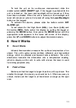
To  lock  the  unit  on  for  continuous  measurement,  slide  the 

middle switch LOCK ON/OFF right. If the trigger is pulled while the 
unit  is  locked  on,  the  laser  and  backlight  will  be  turned  on  if  they 
have been activated. When the unit is locked on, the backlight and 
laser will remain on unless it is turned off using the Laser/Backlight 
button on the keypad. 

To  activate  the  alarms,  please  slide  the  bottom  switch  SET 

ALARM right. 

To set values for the High Alarm (HAL), Low Alarm (LAL) and 

Emissivity  (EMS),  firstly  active  the  display  by  pulling  the  trigger  or 
pressing  the  MODE  button,  then  press  the  MODE  button  until  the 
appropriate  code  appears  in  the  lower  left  corner  of  the  display, 
press the UP and DOWN buttons to adjust the desired values. 

6  How it Works 


How it Works 


Infrared  thermometers  measure  the  surface  temperature  of  an 

object.  The  unit’s  optics  sense  emitted,  reflected,  and  transmitted 
energy,  which  is  collected  and  focused  onto  a  detector.  The  unit’s 
electronics  translate  the  information  into  a  temperature  reading, 
which  is  display  on the  unit. In  units  with  a  laser, the  laser  is  used 
for aiming purposes only. 


Field of View 


Make sure that the target is larger than the unit’s spot size. The 

smaller the target, the closer you should be to it. When accuracy is 
critical,  make  sure  the  target  is  at  least  twice  as  large  as  the  spot 
size. 


Summary of Contents for DIT-130

Page 1: ...1 OPERATING MANUAL NON CONTACT INFRARED THERMOMETER DIT 130 Version 1 5 ...

Page 2: ...witch Emissivity Digitally adjustable from 0 10 to 1 00 MAX MIN DIF AVG rekord LCD with Backlight Automatic range selection Resolution 0 1ºC 0 1ºF Trigger lock High and Low alarm Obtain Emissivity WIDE RANGE APPLICATION Temperature measurements of electric devices food preparation safety and fire inspectors plastic molding asphalt marine and screen printing measure ink and dryer temperature Diesel...

Page 3: ...STANCE SPOT SIZE 10 5 SWITCHING C F LOCK ON OFF AND SET ALARM 10 6 HOW IT WORKS 11 7 MEASUREMENT OPERATION 14 8 DATA LOGGER 15 8 1 STORING DATA 15 8 2 RECALLING DATA 16 8 3 LOG CLEAR FUNCTION 16 9 BATTERY REPLACEMENT 16 10 CLEANING AND MAINTENANCE 17 11 STORAGE 17 12 DISMANTLING AND UTILIZATION 17 13 TECHNICAL DATA 18 14 STANDARD EQUIPMENT 19 15 MANUFACTURER 20 ...

Page 4: ...re of this meter will provide years of reliable service In the present manual we apply three kinds of warnings These are texts in frames which describe possible dangers both for the user and the meter itself The messages starting from the word WARNING describe situations which imply a risk for life or health should the recommendations presented in the present manual not be observed The word ATTENT...

Page 5: ...eful no to let the beam on a reflective surface strike your eye Do not allow the laser light beam impinge on any gas which can explode It is prohibited to operated the meter If it is damaged and completely or partially out of order If it has been stored for an excessive period of time in inadequate conditions e g if it is humid Before commencing a measurement make sure the correct measurement func...

Page 6: ...6 3 Functional description 3 1 Devices description IR sensor Laser pointer beam LCD Display DOWN BUTTON UP BUTTON MODE BUTTON laser backlight button Measurement Trigger Handle Grip Battery Cover ...

Page 7: ...mbol and value C F symbol Auto obtain Emissivity lock and laser on symbols High alarm and low alarm symbol Temperature values for the MAX MIN DIF AVG HAL LAL And TK Symbols for EMS MAX MIN DIF AVG HAL LAL and TK Current temperature value Low battery 3 3 Buttons ...

Page 8: ...8 Up button for EMS HAL LAL MODE button for cycling through the mode loop Down button for EMS HAL LAL Laser Backlight on off button 3 4 MODE Button Function MODE ...

Page 9: ...er is pulled again the unit will begin measuring in the last mode selected Pressing the MODE button also allows you to access the High Alarm HAL Low Alarm LAL Emissivity EMS Each time you Press MODE you advance through the mode cycle Pressing the MODE button also allows you to access the Type K Temp measurement and memory mode LOG The diagram shows the sequence of functions in the MODE cycle HAL L...

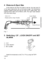
Page 10: ...e for each unit is listed below The focal point for each unit is 914mm 36 The spot sizes indicate 90 encircled energy D S 13 1 Sensor Beam D 30 390 10 130 50 650 mm Distance D to Spot Size S inch 16mm 1 2 15 6 0 4 5 2 2 0 26 Laser Beam S Fig 1 5 Switching C F LOCK ON OFF and SET ALARM C F LOCK ON OFF SET ALARM Select the temperature units o C or o F by using the o C o F switch ...

Page 11: ...button then press the MODE button until the appropriate code appears in the lower left corner of the display press the UP and DOWN buttons to adjust the desired values 6 How it Works How it Works Infrared thermometers measure the surface temperature of an object The unit s optics sense emitted reflected and transmitted energy which is collected and focused onto a detector The unit s electronics tr...

Page 12: ...rest then scan across with an up and down motion until you locate hot spot Reminders Not recommended for use in measuring shiny or polished metal surfaces stainless steel aluminum etc See Emissivity The unit cannot measure through transparent surfaces such as glass It will measure the surface temperature of the glass instead Steam dust smoke etc Can prevent accurate measurement by obstructing the ...

Page 13: ...terial underneath it Measure the temperature of the tape or painted surface Emissivity Values Substance Thermal emissivity Substance Thermal emissivity Asphalt 0 90 to 0 98 Cloth black 0 98 Concrete 0 94 Human skin 0 98 Cement 0 96 Leather 0 75 to 0 80 Sand 0 90 Charcoal po wder 0 96 Earth 0 92 to 0 96 Lacquer 0 80 to 0 95 Water 0 92 to 0 96 Lacquer matt 0 97 Ice 0 96 to 0 98 Rubber black 0 94 Sno...

Page 14: ...Emissivity In the EMS mode press and hold the Trigger and in the same time press the Laser Backlight button twice once short and second one longer until the EMS icon on the left side of LCD blinking At this time ε will appear at the upper side of the LCD IR temperature value will be in the middle of LCD and Type K temperature value is at the lower side of the LCD Contact the Type K probe to the ob...

Page 15: ...easurements some time several minutes is required after the low and before the high temperature measurements are made This is a result of the cooling process which must take place for the IR sensor 8 Data Logger 8 1 Storing Data Your thermometer is capable of storing up to 20 data locations The infrared temperature and temperature scale o C or o F are also stored To store data from an infrared rea...

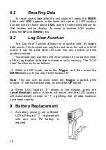
Page 16: ...ocations stored You should only use the LOG clear function if you want to clear all the Log location data that is stored in unit s memory The LOG clear function works as follows 1 While in LOG mode press the Trigger and then press the DOWN button until you reach LOG location 0 Note This can only be done when the Trigger is pulled LOG location 0 cannot be accessed by using the UP button 2 When LOG ...

Page 17: ...manufacturer s specified parts 11 Storage In the case of storage of the device the following recommendations must be observed Make sure the meter and its accessories are dry In the case the meter is to be stored for a prolonged period of time the batteries must be removed from the device 12 Dismantling and utilization Worn out electric and electronic equipment should be gathered selectively i e it...

Page 18: ...6 Other technical data a response time less than 1 second b spectral response 8 14µm c emissivity digitally adjustable from 0 10 to 1 0 d over range indication LCD will show 0L 0L e polarity automatic no indication for positive polarity minus sign for negative polarity f diode laser output 1mW Wavelength 630 670nm class 2 laser product Temperature range Resolution Basic accuracy 50 0 999 9 58 0 99...

Page 19: ...th EMC Note Accuracy Given at 18 to 28 64 to 82 less than 80 RH Field of View Make sure that the target is larger than the unit s spot size The smaller the target the closer you should be to it When accuracy is critical make sure the target is at least twice as large as the spot size 14 Standard equipment The standard set provided by the manufacturer includes the following components The DIT 130 m...

Page 20: ...tee and post guarantee service is the following company SONEL S A ul Wokulskiego 11 58 100 Świdnica Tel 48 74 858 38 60 Fax 48 74 858 38 09 E mail export sonel pl Web page www sonel pl Note Service repairs must be realised solely by the manufacturer Made in China for SONEL S A ...

Reviews: