background image

DIT-500 

– INSTRUKCJA OBSŁUGI 

16 

6.2.8 

Wybór jednostki temperatury 

O

C/

O

Wybrać jednostkę temperatury (

o

C  lub 

o

F) stosując w tym celu 

przycisk 

W GÓRĘ/W DÓŁ


6.3 

Rejestrator danych 

6.3.1   Zapisywanie danych 

Zakupiony przez Państwa miernik temperatury może zachowy-

wać dane dla 100 pomiarów. 

Aby zapisać odczyt pomiaru do pamięci, należy nacisnąć spust 

pomiarowy.  Trzymając  wciśnięty  spust,  należy  naciskać  przycisk 

MODE


dopóki  symbol  LOG  nie  pojawi  się  w  lewym  dolnym  rogu 

wyświetlacza. W tym momencie na górnym polu odczytowym poja-
wi się numer komórki pamięci. 

Skierować urządzenie w kierunku obszaru mierzonego, którego 

temperatura ma  zostać  zapisana  i  nacisnąć  przycisk 

.  Zapisana 

temperatura pojawi się na dolnym polu odczytowym wyświetlacza. 

Aby wybrać inną komórkę pamięci, należy nacisnąć przycisk 

GÓRĘ

 lub 

W DÓŁ

.. 

Jeśli w danej komórce nie ma zapisanej informacji, wówczas na 

dolnym polu odczytowym pojawią się cztery poziome kreski. 

6.3.2  

Przeglądanie danych 

Aby  przywołać  zapisane  uprzednio  dane  po  wyłączeniu  urzą-

dzenia

,  należy  przyciskiem 

MODE


wybrać  przeglądanie  wartości 

MAX (miga MAX na wyświetlaczu). 

Następnie  przyciskami 

W  GÓRĘ/W  DÓŁ


należy  wybrać  tryb 

LOG 

(miga  LOG  na  wyświetlaczu)  oraz  zatwierdzić  wybór  krótkim 

naciśnięciem spustu. LOG przestanie migać a na górnym polu od-
czytowym  pojawi  się  numer  komórki  pamięci.  Na  dolnym  polu  od-
czytowym będzie zapisana temperatura dla tej komórki. 

Celem przejścia do innej komórki pamięci,  należy użyć przyci-

sków 

W GÓRĘ/W DÓŁ


Summary of Contents for DIT-500

Page 1: ...1 INSTRUKCJA OBS UGI 1 USER MANUAL 25 MANUAL DE USO 47 DIT 500 v1 7 05 03 2020...

Page 2: ......

Page 3: ...1 INSTRUKCJA OBS UGI PIROMETR BEZKONTAKTOWY TERMOMETR PRACUJ CY W PODCZERWIENI DIT 500 Wersja 1 7 05 03 2020...

Page 4: ...od 0 10 do 1 00 wy wietlanie temperatury maksymalnej minimalnej redniej i r nicowej pod wietlany wy wietlacz ciek okrystaliczny automatyczny wyb r zakresu rozdzielczo 0 1 C 0 1 F blokada pomiaru alar...

Page 5: ...rto ci MAX MIN DIF AVG 15 6 2 2 Ustawienia emisyjno ci 15 6 2 3 W czenie pomiaru ci g ego LOCK 15 6 2 4 Alarm wysokich warto ci temperatury HAL 15 6 2 5 Ustawienia progu HAL 15 6 2 6 Alarm niskich war...

Page 6: ...rmometr w takich jak obiekty ru chome powierzchnie przewodz ce pr d lub przedmioty w kt rych przypadku trudno o bezpo redni kontakt Prawid owa eksploatacja oraz utrzymanie niniejszego miernika zapewni...

Page 7: ...ch w stron oczu nie wolno dopu ci by wi zka laserowa kierowa a si w stron jakiegokolwiek wybuchowego gazu niedopuszczalne jest u ywanie miernika kt ry uleg uszkodzeniu i jest ca kowicie lub cz ciowo n...

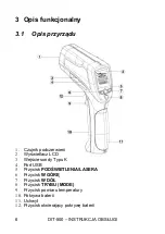
Page 8: ...du 1 Czujnik podczerwieni 2 Wy wietlacz LCD 3 Wej cie sondy Typu K 4 Port USB 5 Przycisk POD WIETLENIA LASERA 6 Przycisk W G R 7 Przycisk W D 8 Przycisk TRYBU MODE 9 Przycisk pomiaru temperatury 10 P...

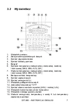
Page 9: ...VG DIF 7 Warto ci temperatury maksymalnej minimalnej redniej i r nicowej MAX MIN AVG DIF 8 Bie ca warto temperatury 9 Symbol zapisu danych 10 Symbol emisyjno ci 11 Wska nik pod czenia sondy K 12 Jedno...

Page 10: ...0 INSTRUKCJA OBS UGI 8 3 3 Przyciski 1 Przycisk w czaj cy i wy czaj cy laser oraz pod wietlenie LCD 2 Przycisk W D dla HAL LAL 3 Przycisk W G R dla HAL LAL 4 Cyklicznie dzia aj cy przycisk MODE TRYB 3...

Page 11: ...ratury pracuj ce w podczerwieni mierz temperatur powierzchni przedmiotu Uk ad optyczny urz dzenia wykrywa wyemitowan odbit i przes an energi kt ra zostaje zebrana i skoncentrowana w detektorze Uk ad e...

Page 12: ...temperatur powierzchni szk a Para py dym itp mog uniemo liwia wykonanie dok ad nych pomiar w na skutek zak ce jakie powoduj w funkcjo nowaniu uk adu optycznego urz dzenia Emisyjno Emisyjno jest termi...

Page 13: ...75 do 0 80 Piasek 0 90 W giel drzewny py 0 96 Ziemia 0 92 do 0 96 Lakier 0 80 do 0 95 Woda 0 92 do 0 96 Lakier matowy 0 97 L d 0 96 do 0 98 Guma czarna 0 94 nieg 0 83 Plastik 0 85 do 0 95 Szk o 0 90...

Page 14: ...oko o siedmiu sekundach od zwolnienia spustu chyba e urz dze nie jest w trybie pomiaru ci g ego Uwagi dotycz ce pomiar w Trzymaj c miernik za jego uchwyt nale y skierowa czujnik podczerwieni w kierunk...

Page 15: ...etlaczu Nale y nacisn przyciski W G R lub W D celem ustawienia po danych warto ci 6 2 Przycisk TRYB MODE W trybie zatrzymania wy wietlanych wynik w HOLD nale y nacisn przycisk MODE kt ry pozwala na do...

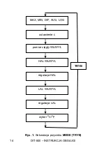
Page 16: ...DIT 500 INSTRUKCJA OBS UGI 14 LAL W WY regulacja HAL MAX MIN DIF AVG LOG wyb r O C O F regulacja LAL ustawienie pomiar ci g y W WY HAL W WY TRYB Rys 1 Sekwencja przycisku MODE TRYB...

Page 17: ...celem w czenia lub wy czenia pomiaru ci g ego Nast pnie nale y nacisn spust pomiarowy celem przej cia do pomiaru ci g ego Przyrz d b dzie w spos b ci g y wy wietla tem peratur dop ki spust pomiarowy...

Page 18: ...ma zosta zapisana i nacisn przycisk Zapisana temperatura pojawi si na dolnym polu odczytowym wy wietlacza Aby wybra inn kom rk pami ci nale y nacisn przycisk W G R lub W D Je li w danej kom rce nie ma...

Page 19: ...do kom rki 000 Uwaga Powy sze mo e zosta wykonane wy cznie w wczas gdy spust jest wci ni ty Kom rka 000 nie jest dost pna poprzez przy cisk W G R gdy kom rka 000 jest pokazana na wy wietlaczu nale y n...

Page 20: ...jest niedostateczne na wy wietlaczu pojawi si symbol oznaczaj cy e wymagana jest wymiana na now bateri 9V Uwaga Dokonuj c pomiar w przy wy wietlonym mnemoniku baterii nale y si liczy z dodatkowymi ni...

Page 21: ...iernych 9 Magazynowanie Przy przechowywaniu przyrz du nale y przestrzega poni szych zalece upewni si e miernik jest suchy przy d u szym okresie przechowywania nale y wyj bateri 10 Rozbi rka i utylizac...

Page 22: ...8 0 999 9 50 1 0 1 0 1 50 20 58 68 2 5 4 5 1000 1600 1000 2912 1 1 20 400 68 752 1 0 w m 1 lub 1 8 400 800 752 1472 1 5 w m 2 lub 3 6 800 1600 1472 2912 2 5 w m Temperatura otoczenia w zakresie od 23...

Page 23: ...ilgotno robocza 10 do 90 wilgotno przechowywania 80 j pami 100 kom rek k po czenie z PC interfejs USB l zasilanie bateria 9V NEDA 1604A lub IEC 6LR61 m bezpiecze stwo spe nia warunki dla kompatybilno...

Page 24: ...3 Serwis Prowadz cym serwis gwarancyjny i pogwarancyjny jest SONEL S A ul Wokulskiego 11 58 100 widnica tel 74 858 38 00 Biuro Obs ugi Klienta e mail bok sonel pl internet www sonel pl Wyprodukowano w...

Page 25: ...MIERNIKI DO POMIAR W WIELKO CI ELEKTRYCZNYCH ORAZ PARAMETR W SIECI ENERGETYCZNYCH o mierniki napi cia o mierniki pr du w tym r wnie mierniki c gowe o mierniki rezystancji o mierniki rezystancji izola...

Page 26: ...nia odst p w czasu mi dzy wzorcowaniami przyrz d w pomiarowych Firma SONEL S A zaleca dla produkowanych przez siebie przyrz d w wykonywanie po twierdzenia metrologicznego nie rzadziej ni co 12 miesi c...

Page 27: ...25 USER MANUAL NON CONTACT INFRARED THERMOMETER DIT 500 Version 1 7 05 03 2020...

Page 28: ...table from 0 10 to 1 00 MAX MIN AVG DIF temperature displays backlight LCD display automatic selection range display resolution 0 1 C 0 1 F trigger lock set high and low alarms data logger LOG transmi...

Page 29: ...nctions of MODE button 36 6 2 1 MAX MIN DIF AVG display 38 6 2 2 Emissivity adjustment 38 6 2 3 Continuous measurement LOCK on off 38 6 2 4 High alarm HAL on off 38 6 2 5 HAL adjustment 38 6 2 6 Low a...

Page 30: ...ricity current or the objects which are uneasy to be touched Proper use and care of this meter will provide years of reliable service In the present manual we apply three kinds of warnings These are t...

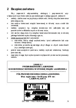
Page 31: ...al Be careful not to let the beam on a reflective surface strike your eye Do not allow the laser light beam impinge on any gas which can explode It is prohibited to operate the meter If it is damaged...

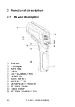
Page 32: ...NUAL 30 3 Functional description 3 1 Device description IR sensor LCD Display TYPE K IN USB IN LIGHT LASER BUTTON UP BUTTON DOWN BUTTON MODE BUTTON MEASUREMENT TRIGGER BATTERY COVER HANDLE GRIP BATTER...

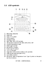
Page 33: ...DIF symbols Temperature values for the MAX MIN AVG DIF Current temperature value Data logger symbol Emissivity symbol Probe Type K symbol O C or O F symbols High alarm HAL and low alarm LAL symbols U...

Page 34: ...DIT 500 USER MANUAL 32 3 3 Buttons Laser Backlight on off button Down button for HAL LAL Up button for HAL LAL Cyclic MODE button 3 4 2 1...

Page 35: ...ared Infrared thermometers measure the surface temperature of an object The unit s optics sense emitted reflected and trans mitted energy which is collected and focused onto a detector The unit s elec...

Page 36: ...the surface temperature of the glass instead Steam dust smoke etc Can prevent accurate measure ment by obstructing the unit s optics Emissivity Emissivity is a term used to describe the energy emittin...

Page 37: ...0 90 Copper oxides 0 78 Mortar 0 89 to 0 91 Iron oxides 0 78 to 0 82 Brick 0 93 to 0 96 Textiles 0 90 5 Measurement operation Hold the meter by its handle grip and point it toward the sur face to be m...

Page 38: ...value MIN value DIF value AVG value or LOG value In the measuring time if the Type K thermocouple is not connected you can adjust by pressing up down key In the HOLD mode you can adjust O C O F by pre...

Page 39: ...DIT 500 USER MANUAL 37 LAL on off HAL adjustment MAX MIN DIF AVG LOG O C O F LAL adjustment adjustment LOCK on off HAL on off MODE Fig 1 Sequence of MODE button...

Page 40: ...for continuous monitoring of temperatures Press the UP button or DOWN button to turn on or off Press the measurement trigger to confirm the lock measurement mode The IR thermometer will continuously...

Page 41: ...off press the MODE button until blinking MAX appears on the LCD Press the UP or DOWN button to call blinking LOG symbol on LCD Press trigger to accept A LOG location number will be shown on upper disp...

Page 42: ...ment data to the PC via USB For turn on or off USB function press LIGHT LASER button until USB sign appears in the right lower corner of the LCD The USB function turn on Then press the LIGHT LASER but...

Page 43: ...se only manufacturer s specified parts 9 Storage In the case of storage of the device the following recommenda tions must be observed Make sure the meter and its accessories are dry In the case the me...

Page 44: ...0 1 0 1 50 20 58 68 2 5 4 5 1000 1600 1000 2912 1 1 20 400 68 752 1 0 m v 1 or 1 8 400 800 752 1472 1 5 m v 2 or 3 6 800 1600 1472 2912 2 5 m v Operating temperature of 23 to 25 73 to 77 m v means mea...

Page 45: ...4 to 140 i relative humidity 10 90 RH operating 80 RH storage j memory 100 cells k PC interface USB l power supply 9V battery NEDA 1604A or IEC 6LR61 m safety CE Comply with EMC n weight 350g o size 2...

Page 46: ...s guarantee and post guarantee service is the following company SONEL S A Wokulskiego 11 58 100 widnica Poland Tel 48 74 858 38 60 Fax 48 74 858 38 09 E mail export sonel pl Web page www sonel pl Note...

Page 47: ...electrical and non electrical parameters METERS FOR MEASUREMENTS OF ELECTRICAL PARAMETERS o voltage meters o current meters including clamp meters o resistance meters o insulation resistance meters o...

Page 48: ...r determination of calibration intervals of measuring instruments SONEL S A recommends pe riodical metrological inspection of the instruments it manufactures no less frequently than once every 12 mont...

Page 49: ...47 MANUAL DE USO PIR METRO TERM METRO SIN CONTACTO EN INFRARROJOS DIT 500 Versi n 1 7 05 03 2020...

Page 50: ...emperatura m xima m nima media y diferencial pantalla de cristal l quido iluminada de fondo selecci n de rango autom tica resoluci n 0 1 C 0 1 F bloqueo de medici n alarma para valores de temperaturas...

Page 51: ...es MAX MIN DIF AVG 61 6 2 2 Configuraci n de emisividad 61 6 2 3 Desactivaci n de la medici n continua LOCK 61 6 2 4 Alarma de valores altos de temperatura HAL 61 6 2 5 Configuraci n de l mite HAL 61...

Page 52: ...viles superficies conductoras el ctricas u objetos en cuyo caso es dif cil entrar en contacto directo La explotaci n y el mantenimiento adecuados de este instrumento aseguran muchos a os de su servic...

Page 53: ...la superficie catadi ptrica a los ojos no permitir que el haz de l ser se dirija hacia cualquier gas explosivo es inaceptable es el uso de medidor da ado y totalmente o parcialmente defectuso medidor...

Page 54: ...dispositivo 1 Sensor de infrarrojos 2 Pantalla LCD 3 Entrada de sonda tipo K 4 Puerto USB 5 Bot n DE ILUMINACI N L SER 6 Bot n ARRIBA 7 Bot n ABAJO 8 Bot n MODO MODE 9 Bot n de medici n de temperatura...

Page 55: ...AVG DIF 7 Valores de la temperatura m xima m nima media y diferencial MAX MIN AVG DIF 8 Valor de temperatura actual 9 S mbolo de registro de datos 10 S mbolo de emisividad 11 Indicador de conexi n de...

Page 56: ...T 500 MANUAL DE USO 54 3 3 Botones 1 Bot n para encender o apagar el l ser o la iluminaci n LCD 2 Bot n ABAJO para HAL LAL 3 Bot n ARRIBA para HAL LAL 4 Bot n de funcionamiento c clico MODO MODE 3 4 2...

Page 57: ...mperatura que trabajan en infrarrojos miden la temperatura de la superficie de un objeto El sistema ptico del dispositivo detecta la energ a emitida reflejada y transmitida que es acumulada y concentr...

Page 58: ...cie del vidrio Vapor polvo humo etc pueden impedir mediciones precisas debido a perturbaciones que causan en el funcionamiento del sistema ptico del dispositivo Emisividad La emisividad es un t rmino...

Page 59: ...a 0 82 Ladrillo 0 93 a 0 96 Textiles 0 90 5 Realizaci n de mediciones Coger el medidor por el mango y dirigirlo hacia la superficie que debe ser medida Apretar y mantener presionado el gatillo de medi...

Page 60: ...rarrojo 6 Funciones especiales 6 1 Funcionalidad Durante la medici n si pulse otra vez el bot n MODE se mostrar el valor m ximo el valor m nimo el valor diferencial el valor medio o el n mero de c lul...

Page 61: ...do de alarma de las temperaturas altas HAL regulaci n de alarma de las temperaturas altas encendido apagado de alarma de las temperaturas bajas LAL regulaci n de alarma de las temperaturas bajas selec...

Page 62: ...DIT 500 MANUAL DE USO 60 LAL ON OFF regulaci n HAL MAX MIN DIF AVG LOG selecci n O C O F regulaci n LAL configuraci n medici n continua ON OFF HAL ON OFF MODO Fig 1 Secuencia del bot n MODO MODE...

Page 63: ...es especialmente til para el seguimiento continuo de temperaturas Pulse el bot n ARRIBA o ABAJO para activar o desactivar la medici n continua A continuaci n pulse el gatillo de medici n para pasar a...

Page 64: ...ampo superior de la pantalla aparecer el n mero de c lula de memoria Apunte el dispositivo hacia el rea medida cuya temperatura se debe guardar y pulse el bot n La temperatura guardada aparecer en el...

Page 65: ...el bot n de la flecha indicada hacia ABAJO hasta llegar a la c lula 000 Nota Esto se puede hacer s lo cuando el gatillo est pulsado La celda 000 no est disponible a trav s del bot n ARRIBA cuando la c...

Page 66: ...cesario cambiar la pila por una nueva de 9V Nota Haciendo mediciones en el mostrado mnem nico de la bater a hay que tener en cuenta las incertidumbres adicionales de medici n no especificadas o el fun...

Page 67: ...Durante el almacenamiento del instrumento hay que seguir las siguientes instrucciones asegurarse de que el medidor est seco durante un almacenamiento prolongado se debe quitar la bater a 10 Desmontaj...

Page 68: ...99 9 50 1 0 1 0 1 50 20 58 68 2 5 4 5 1000 1600 1000 2912 1 1 20 400 68 752 1 0 w m 1 o 1 8 400 800 752 1472 1 5 w m 2 o 3 6 800 1600 1472 2912 2 5 w m Temperatura del ambiente en el rango del 23 a 25...

Page 69: ...140 i humedad relativa 10 al 90 humedad de almacenamiento 80 j memoria de 100 c lulas k conexi n con PC interfaz USB l alimentaci n pila 9V NEDA 1604A o IEC 6LR61 m seguridad cumple con los requisito...

Page 70: ...antenimiento El servicio de garant a y postgarant a lo presta SONEL S A Wokulskiego 11 58 100 widnica Polonia tel 48 74 858 38 60 fax 48 74 858 38 09 E mail export sonel pl Web page www sonel pl Fabri...

Page 71: ......

Page 72: ......
Reviews: