background image


KT-

560 ● KT-650 ● KT-670 – USER MANUAL 

2  Safety 

Before you proceed to operate the camera, acquaint yourself thoroughly with the present manual and 
observe the safety regulations and specifications defined by the manufacturer.  


Any application that differs from those specified in the present manual may result in a damage to 
the device and constitute a source of danger for the user. 


The camera must not be used in rooms where special conditions are present e.g. fire and explo-
sion risk.  


It is forbidden to use damaged or malfunctioning camera and is partially or fully out of order.  


In case the camera is not used for a long time, its battery should be removed.  


It is not allowed to use the camera with half-closed or opened battery cover and do not use any 
other power adapter than the one supplied with the camera.  


Repairs may be carried out only by an authorised service point. 

 
KT  series  Thermal  Imagers  are  designed  to  measure  and  record  the  images  in  the  infrared.  The 
camera is constructed in a manner which gives you maximum performance and safety at work, how-
ever the following precautions must be adhered to at all times (in addition to any advised precautions 
applicable at the relevant work site or work area): 


Keep the camera steady during operation. 


Do not use the camera in ambient temperatures exceeding its operation and storage temperature 
ranges. 


Do not direct the camera toward very high intensity radiation sources such as the sun, la-

sers or welding arcs etc. 


Do not expose the camera to dust and moisture. When operating the device near water, ensure 
that it is adequately guarded against splashes. 


When  the  camera  is  not  in use  or  is  to  be  transported,  ensure  that  the  unit  and  its  accessories 
are stored in the protective carry case. 


Do not obstruct the speaker holes in the camera’s body. 


Do  not  re-switch  on  the  imager  before  30  seconds  after  switching  it  off  and  do  not  remove  the 
battery when the imager is on. 


Do  not  throw,  knock  or  shake  intensely  the  camera  and  its  components  in  order  to  avoid  the 
damage.  


Do not attempt to open the imager's body, as this action will void the warranty. 


Keep the SD memory card for the exclusive use of the camera.  


During operation, if the camera is to be moved from hot/cold place to cold/hot place, e.g. from in-
side/outside to outside/inside of a room, switch the imager off and leave it in the new workplace 
for  20  minutes,  then  turn  it  on  and  start  normal  operation  with  an  accurate  temperature  meas-
urement. Sudden and rapid changes in ambient temperature may cause fault temperature meas-
urement and even damage camera’s IR detector. 


FPA  calibration  (FPA 

–  Focal  Plane  Array):  in  order  to  ensure  accurate  temperature  measure-

ment, the FPA detector was calibrated in different temperature points. After switching the imager 
on, it performs auto calibration procedure every once in a while. During the calibration, for about 

1 second, 

the device does not respond to us

er’s activity

, during this time the sound of a shut-

ter clicking twice is heard. Additionally, calibration can be performed manually at any time.  


During 

imager operation its housing temperature increases and it’s a normal phenomenon. 


Summary of Contents for KT-560

Page 1: ...USER MANUAL THERMAL IMAGER KT 560 KT 650 KT 670...

Page 2: ......

Page 3: ...USER MANUAL THERMAL IMAGERS KT 560 KT 650 KT 670 SONEL S A Wokulskiego 11 58 100 widnica Poland Version 2 01 18 02 2022...

Page 4: ...8 for the design manufacturing and servicing Due the continuous development of our products we reserve the right to introduce changes and im provements in the thermal imaging camera and in the softwar...

Page 5: ...aving images 20 5 1 Taking images 20 5 2 Panorama stitching 21 5 3 Super resolution 21 5 4 Timed shooting 22 6 Recording and storing infrared videos 23 6 1 Video recording 23 6 2 Timed video recording...

Page 6: ...e 38 8 22 Synchronous data 38 8 23 Format SD card 38 8 24 Recovery 38 9 Accurate temperature measurement 39 10 Port connection 40 10 1 Micro HDMI port 40 10 2 USB port 40 10 3 LAN port 41 11 SD card 4...

Page 7: ...T 560 KT 650 KT 670 USER MANUAL 5 19 Accessories 51 19 1 Standard accessories 51 19 2 Optional accessories 52 20 Manufacturer 53 21 Exemplary emissivity coefficient values 54 22 Laboratory services 55...

Page 8: ...infrared visual and PIP picture in picture the camera has a mode for mixing images overlapping and blending outlines of the visual image on the infrared image User can take and store static images or...

Page 9: ...c Do not expose the camera to dust and moisture When operating the device near water ensure that it is adequately guarded against splashes When the camera is not in use or is to be transported ensure...

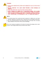
Page 10: ...RNING THE CAMERA ON UNTIL IT REACHES THE POINT OF BEING FULLY OPERATIONAL IT IS FORBIDDEN TO AIM IT AT HUMAN AND ANIMALS NOTE The thermal imager has no parts that could be repaired or modified by its...

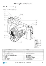
Page 11: ...programmable 11 Viewfinder focus adjustment 3 Laser ranging button 12 Power On Off button 4 Focus adjustment buttons T zoom in W zoom out 13 Image mode rotary selector 5 Trigger button freeze save ima...

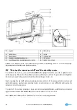
Page 12: ...ff button 12 for around 2 seconds A splash screen will be displayed followed by the self test procedure of the device When the procedure is completed the camera is ready to be used and real time infra...

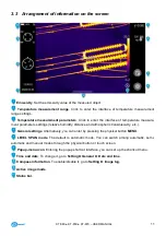
Page 13: ...tings relative humidity distance and atmospheric transmissivity etc General settings Alternatively you can enter by pressing the physical button MENU LEVEL SPAN mode The default is automatic mode You...

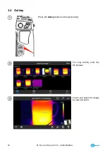
Page 14: ...KT 560 KT 650 KT 670 USER MANUAL 12 3 4 Gallery Press the Gallery button on the device body You may directly enter the file browser Touch and select the image to view and edit it...

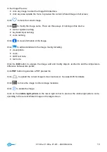
Page 15: ...age Click to add annotations to the image mainly including visual photo voice OCR text note text note Click the Edit button to analyze the image add and modify objects isotherms and the temperature di...

Page 16: ...ainly for some shortcut operations in Real time Images including image analysis temperature measurement analysis pa rameter modification graphic stroke isotherm temperature difference and other shortc...

Page 17: ...uding brightness volume Bluetooth Wi Fi laser panoramic stitching and su per resolution settings 3 7 Laser rangefinder Laser rangefinder can be activated while being in real time mode by pressing butt...

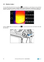
Page 18: ...ing the camera operation in real time mode the image can be displayed on either the LCD screen or in the viewfinder Toggle between these two display modes with button 1 4 2 Image modes The camera capt...

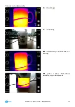
Page 19: ...T 650 KT 670 USER MANUAL 17 There are four modes available IR infrared image VL visual image MIF infrared image combined with visu al image PIP picture in picture both infrared and visual images are d...

Page 20: ...the screen other than the menu to return to the real time interface Then aim the center cursor at the measured object for temperature measurement 4 4 Focus adjustment You can push the joystick up and...

Page 21: ...g the calibration for about 1 second the device does not respond to user s activity during this time the sound of a shutter clicking twice is heard Calibration can be performed manually at any time In...

Page 22: ...space to save a file on SD card or when a saving error occurs proper information will be displayed on screen Saved thermal image file name is IRIxxxxx jpg where xxxxx are digits Additionally a separat...

Page 23: ...g function In this function two or more im ages from the device are stitched into one panoramic This function needs to be supported by ThermoAna lyze 3 software Image Stitching 5 3 Super resolution Us...

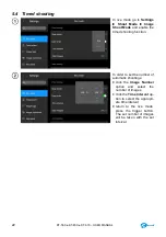
Page 24: ...the timed shooting function In order to set the number of automatic shootings click the Image Number option and select the number of images click the Time Interval op tion to select the appropri ate t...

Page 25: ...recording Press the button briefly to stop recording and save the file 6 2 Timed video recording Go to Settings Timed video recording Click the delay time item and select the delay time Click the dura...

Page 26: ...display of the highest temperature lowest tem perature average temper ature value and center display function Press and hold any analysis object An object menu will pop up The following func tions are...

Page 27: ...ect ed Move any node to change the area of the analysis object 7 1 3 Linear analysis object Up to 3 linear analysis ob jects can be added and dis played simultaneously in live mode 7 1 4 Palette switc...

Page 28: ...g press the stroked ob ject The object menu will appear In the menu you can ana lyze the added strokes delete them and set their emissivity 7 1 6 Difference temperature analysis Add at least two analy...

Page 29: ...ame time During the adjustment process the image dimming changes synchronously SPAN adjustment The SPAN can be adjusted by the Left and Right key of the joystick When the Right key is pressed the Tmax...

Page 30: ...other attributes Save the settings after ex iting Parameter introduction Reflection temperature Editable by the user The value range 40 2000 Target distance Editable by the user The value range 0 100...

Page 31: ...ers and the image will be zoomed out When the infrared image is enlarged the infrared image can be moved using a single finger 7 2 3 Creating a PDF Press the Gallery button to enter the gallery browsi...

Page 32: ...the gallery browsing in terface and click Video to enter the video interface Tap the play button in the center of the screen to start playing the film Tap the screen to display the short film playback...

Page 33: ...AL 31 7 3 Isotherms Click the shortcut menu and slide the object interface down to the iso therm bar High isotherm real time video image mode Low isotherm real time video image mode Intra field iso th...

Page 34: ...time video image mode Turn off the iso therm display 7 4 Custom emissivity Click to enter emissivity and select Custom Customize the parameters according to your own re quirements Slide the cor respo...

Page 35: ...C as required Return to the real time video interface If the temperature in the scene is higher than 35 6 C the equipment will give an audible alarm Click the alarm icon to immediately turn off the hi...

Page 36: ...some watermark options including logo watermark date watermark humidity watermark GPS orientation emissivity emission temperature and target distance watermark Take an example image and display it in...

Page 37: ...adjusted other parameters should be consistent with the factory values 8 11 Password lock Users may utilize the password protection function in device startup according to their own operating habits 8...

Page 38: ...valid hotspot name i e Camera and password i e 12345678 and click OK to save Then return to live mode and pull up to pop up the shortcut menu Enable AP function After the AP is successfully enabled t...

Page 39: ...Then it can be used together with supporting software It needs to be used together with PC side applica tion software 8 16 Bluetooth Turn on a Bluetooth head set press and hold the Call Button for 3...

Page 40: ...e software list of the third party used by this device 8 20 Date and time Manually set the system date and time 8 21 Language Multiple languages are available for switching 8 22 Synchronous data Inser...

Page 41: ...tion emitted directly by the measured object reflected the ambient radiation reflected from the surface of the measured object For the camera the sum of the emitted and reflected radiation equals 1 Th...

Page 42: ...HDMI ports Connect the HDMI cable to the camera Let the HDMI logo of the Micro HDMI plug facing the front of the device and insert the plug Connect the HDMI cable to the HDMI IN port of the HD monitor...

Page 43: ...e open menu options and click button to enable LAN con nection Run ThermoAnalyze 3 enter the video analysis interface select the device model and enter the correct IP address Successfully connect with...

Page 44: ...is set in the upper position to allow writing deleting 11 1 Installing SD card in the camera NOTE Turn off the camera before installing SD card To install an SD card in the camera unlock the security...

Page 45: ...nlock the security lid by sliding the latch on the com partment lid 1 and then open the lid by pulling the second latch 2 Next insert and press the SD card deeper into its slot until it clicks and the...

Page 46: ...ndard lens and then insert the extended lens Rotate the extended lens counterclockwise un til hearing the click sound indicating that the lens is installed successfully In order to remove the extended...

Page 47: ...in real time 13 3 Charging batteries When the camera is turned off connecting the AC adapter and starting the charging procedure is signaled by the LED charging indicator embedded in the camera on of...

Page 48: ...d by sliding the latch on the compart ment lid 1 and then open the lid by pulling the second latch 2 Push the battery lock lever above the battery and the battery will partially slide out of the compa...

Page 49: ...cal damages Such damages can contribute to permanent damage of those type of batteries and thus the ignition Any interference in the structure of the bat tery may lead to its damage Shorting poles and...

Page 50: ...ght fogged or contaminated Use professional equipment to clean the front end of visible light Inaccurate temperature measurement Failure in focusing on the target Focus manually or automatically to ma...

Page 51: ...points 12 lines 12 areas Temperature indication min max average Isotherm Tem perature alarm Smart stroke 16 points 16 lines 16 areas Temperature indication min max aver age Isotherm Temperature alarm...

Page 52: ...ur faces of optical lens with fingers be cause fouling left with fingerprints can be harmful to coatings and glass of the lens Chemical agents must not be used for cleaning the optical viewfinder and...

Page 53: ...Follow local regulations related to disposing of packaging used up batteries and rechargeable bat teries 19 Accessories The current list of accessories can be found on the manufacturer s website 19 1...

Page 54: ...560 WAADAO8V560 Wide angle IR lens 45 4 34 8 13 mm for KT 650 670 WAADAO13V670 Tele IR lens 11 2 8 4 33 mm for KT 560 WAADAO33V560 Tele IR lens 11 3 8 5 55 mm for KT 650 670 WAADAO55V670 Power supply...

Page 55: ...Manufacturer The manufacturer and provider of warranty and post warranty services for this instrument is SONEL S A Wokulskiego 11 58 100 widnica Poland tel 48 74 858 38 60 fax 48 74 858 38 09 E mail...

Page 56: ...idized 0 65 copper oxidized black 0 88 copper polished 0 07 copper polished annealed 0 01 0 02 brass 0 10 brass oxidized 0 61 nickel polished 0 05 lead polished 0 08 lead grey 0 28 lead oxidized 0 63...

Page 57: ...imagers o luxmeters The Calibration Certificate is a document that presents a relation between the calibration standard of known accuracy and meter indications with associated measurement uncertaintie...

Page 58: ...KT 560 KT 650 KT 670 USER MANUAL 56 NOTES...

Page 59: ......

Page 60: ...SONEL S A Wokulskiego 11 58 100 widnica Poland tel 48 74 858 38 60 fax 48 74 858 38 00 e mail sonel sonel pl www sonel pl...

Reviews: